Tek-Tips is the largest IT community on the Internet today!

Members share and learn making Tek-Tips Forums the best source of peer-reviewed technical information on the Internet!

  • Congratulations cowski on being selected by the Eng-Tips community for having the most helpful posts in the forums last week. Way to Go!

Masonry Bearing Plate

Status
Not open for further replies.

SteelPE

Structural
Joined
Mar 9, 2006
Messages
2,771
Location
US
I am in the process of checking some shop drawings for a masonry building I designed. The building is large and has an expansion joint in the middle. With the expansion joint comes a set of large bracing. For collectors we are using W18x55 beams (which are very long, but lightly loaded). The end reaction for these beams are roughly 6 kips.

This support beam ends up at the but end of a wall (framed perpendicular to the wall because it’s at an expansion joint). We have had some bad luck with cracking of masonry walls in the past at lintel locations. Attached is the detail we gave in our contract documents. I am wondering if there is a better way to detail this connection before I release the shop drawings?

Note, axial load at this end of the beam is virtually maybe 1.5 kips due to out-of-plane loading of the wall.
 
 https://files.engineering.com/getfile.aspx?folder=c8cf320a-0caf-49da-88f3-9ef1c242238d&file=Expansion_Beam_Detail.pdf
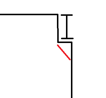
Follow the cracks. What kind of cracking are you trying to prevent? Is it the red line in the attached image? If so, I've done a short bond beam under the bearing plate that develops into the wall.

Capture_x0vr8j.png
 
I was thinking of cracking in the other direction due to prying of the beam. Maybe this is a little extreme as there is 300' of wall perpendicular to the beam. The crack you show may be more likely...... maybe a bond beam is best.

With regards to lintels, we switched to a bolted connection years ago and it seems to have alleviated the issue.
 
1) Much depends on the type of crack that you're hoping to avoid. Is it phamENG's?

2) Your detail is what I've see most often except that I usually see it with beam stiffeners at the back of the beam. An inherent difficulty with the detail is that, when the beam develops end curvature, it forces much of the beam reaction towards the interior face of the wall where it will promote spalling. I'm not sure if this is true or not but, in my mind, the inclusion of the stiffener directs at least some of the load to the interior or the wall where the stiffener is.

3) To help address #2, I've seem some folks include a narrow bearing bar beneath the stiffener to direct the reaction to the interior of the wall.

4) I've seen some folks detail a clip assembly welded to the plate that would, in theory, allow some axial slip to occur at the joint.

5) As always, a stiff beam that doesn't deflect a whole lot is usually your friend.
 
I have observed some concerns in a similar detail. My understanding of the issue led me to believe that excessive heat was induced into the connection during welding which cause spalling of the masonry at the connection. I would recommend welding to the minimum required with as small as a fillet as possible. I would also center the embed plate and headed studs, and provide a bond beam with continuous reinforcement on either side of the HSA's.
 
To push the reaction toward the center of the wall I go for as much beam bearing as I can get, center the bearing plate, and grout a two or more cells below the bearing.

I then convince myself that the beam will not load at the edge of the wall and that this reduces the likelihood of cracking.
 
Status
Not open for further replies.

Part and Inventory Search

Sponsor

Back
Top