I am in the process of checking some shop drawings for a masonry building I designed. The building is large and has an expansion joint in the middle. With the expansion joint comes a set of large bracing. For collectors we are using W18x55 beams (which are very long, but lightly loaded). The end reaction for these beams are roughly 6 kips.
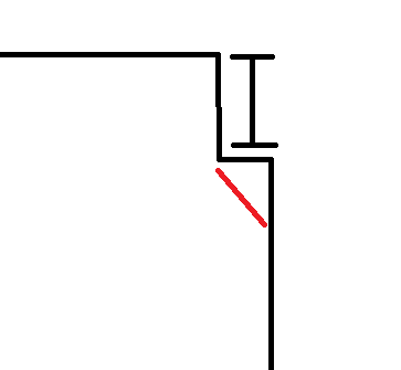
This support beam ends up at the but end of a wall (framed perpendicular to the wall because it’s at an expansion joint). We have had some bad luck with cracking of masonry walls in the past at lintel locations. Attached is the detail we gave in our contract documents. I am wondering if there is a better way to detail this connection before I release the shop drawings?
Note, axial load at this end of the beam is virtually maybe 1.5 kips due to out-of-plane loading of the wall.

