Tek-Tips is the largest IT community on the Internet today!

Members share and learn making Tek-Tips Forums the best source of peer-reviewed technical information on the Internet!

  • Congratulations cowski on being selected by the Eng-Tips community for having the most helpful posts in the forums last week. Way to Go!

LTB mode with tension-compression bracing 4

Status
Not open for further replies.

Italo01

Structural
Joined
Sep 4, 2021
Messages
169
Location
BR
Hello,

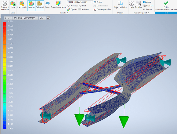
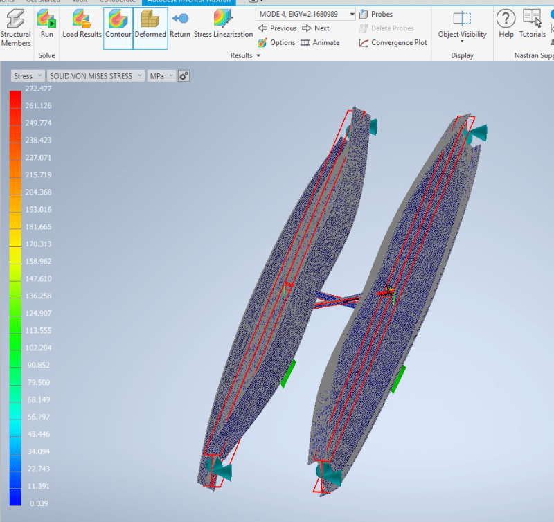
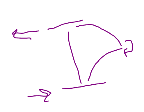
If i have two Beams with Tension-Compression bracing, what preventing them to buckling laterally to oposite sides. I see that the point of contact of the two bracing bars move for this failure mode, so a bolt connecting the two bars would be the only thing preventing this type of failure? If it is, how to determine if this bolt is adequate?

Thank you.
 
 https://files.engineering.com/getfile.aspx?folder=ac9c7b65-d504-4519-8ada-de1e7f75877e&file=Bracing.jpeg
Can someone explain me how do i select a quote on my reply?
 
KootK said:
3) They do not brace the individual beams against a purely torsional buckling mode. But, then, that's a higher energy buckling mode than is LTB. So much so that I suspect that it's often irrelevant.

Sounds like lateral bracing at the shear centre. Often better than nothing but just as often not as effective as a full brace as anticipated by the code equations for reduced effective length.

Edit: Actually not bad for shear centre loading but not great for top flange load.
 
Italo01 said:
Can someone explain me how do i select a quote on my reply?

1. Copy and paste the comment in the reply area.
2. Copy the comment you have moved.
3. Click the button with the guy in the blue shirt with a quote overhead (see below).
When he asks Who? type the name of the person you are quoting.
Capture_v3qcsb.png

4. Preview (optional)
5. Submit Post.

BA
 
KootK said:
Thank you for the discussion and for reporting back to let me/us know that we've reached a consensus.
I've done some computational buckling analysis. Pretty much confirming what you had said.

A pair of crossed angle bracing a beam in the centre will prevent the normal first mode of single span buckling on both beams, pushing the critical buckling modes into the to the second mode of a single span. (AKA the effective LTB length is halved.)
The first eigenvalue of buckling goes from 0.43 to 1.5 with the bracing. Buckling loads are roughly as expected as per you favourite code and taking into account the relevant modifications to the reference buckling moment.

2_mak4fu.png

For what it is worth the torsional buckling mode as pictured by Italo01 isn't completely out of the picture and it comes in at 2.15. Though beam pair buckling occurs marginally before this. It seems unlikely but still conceivable that for some member configurations torsional buckling precedes the 2nd single beam buckling mode, enough reason for me to put the bolt in there.

3_rd9shm.png


KootK said:
The next bit of the fun, for me at least, will be working up a formula for the bolt shear. Tentatively, this is what I've got:

1) Under OP's buckling mode, there actually is no axial force in the braces. Only shear and bending.

2) The bolt shear would be [2 x F / sin (theta)]. [F] being the lateral flange restraint forces and [theta] being the angle that the braces make with the horizontal.
Not sure about this one. I think there is axial and shear and bending which it 'cancelling out' in the closed loop being considered. Give the only input force is the lateral load of compression flange(s) being considered this is the only net load on the restraint preventing the mechanism forming. (The bolt.)

Though it is all a bit moot, as discussed the bolt is not required and even if it was it would be more than strong enough even with more conservative assumptions. Further discussion on this is closer to mechanical than structural.
 
Great analysis, human 909.
 
Italo01 said:
Great analysis, human 909.
Thanks. But I'm not sure that I deserve it. I let the computer and Nastran In-CAD do the grunt work.
 
In this analysis you didn't consider the constraint created by thr bolt on the bracings, correct?

Could you include to check the influence og yhe bolt om this failure and Kootk's supposition that the bolt will have no effect?


Italo01 said:
In this analysis you didn't consider the constraint created by thr bolt on the bracings, correct?
I did consider the effect of the bolt. Without the bolt you picture buckling behaviour occurs as the 3rd buckling mode. It is preceded by the full sine wave beam buckling as shown and narrowly proceeded by the beam pair buckling in a half sign wave. As it is the 3rd buckling mode it is not the critical mode and the bolt has no effect in my specific analysis and I'd suspect this would largely hold true for most similar beam bracing design scenarios. Though as already said, I'd put the bolt in.
 
steveh49 said:
Sounds like lateral bracing at the shear centre.

Yeah, that's a keen observation.

steveh49 said:
Often better than nothing but just as often not as effective as a full brace as anticipated by the code equations for reduced effective length.

1) I would say that it would be a massive improvement over "nothing" for what I expect is the context of this thread: long, slender bridge girders with the bracing applied at multiple points along the span.

2) Shear center bracing will be less effective than bracing the "flange which would move the most". That said:

a) The relative effectiveness of the approaches will tend to converge as more slender beams are considered and the center of LTB rotation moves further from the flange which would move the most.

b) The critical thing, in my mind, is not that the bracing be the most efficient scheme possible but, rather, that it be sufficient to preclude the considered buckling mode from governing under the applied loads.

 
human909 said:
Not sure about this one. I think there is axial and shear and bending which it 'cancelling out' in the closed loop being considered. Give the only input force is the lateral load of compression flange(s) being considered this is the only net load on the restraint preventing the mechanism forming. (The bolt.)

With reference to the half model FBD below, I believe that I can logically prove that there will be no axial load in the braces. Try this on for size:

1) Because of symmetry, if there is axial load in the braces, it is the same load for both braces.

2) Because of symmetry, there can be no vertical shear crossing the bolted joint.

3) Because there is no vertical shear crossing the bolted joint, if there are axial forces in the braces, their vertical components must oppose one another at the joint and cancel.

4) If the vertical components of the brace forces oppose one another at the joint then, by definition, their horizontal components would be additive.

5) There cannot be a non-zero, aggregate, horizontal load component at the joint because the the flange restraint forces are already in horizontal equilibrium without such components.

All that = no axial forces in the braces.

I'm doing by best Aristotle here. I started off sketching it but it's oddly difficult to sketch a logical fallacy without making a flip book out of it.

Perhaps it's valid to simply say that the only net load applied to the half model is a moment. Therefore the only net reaction supplied by the other half of the model must also be a moment.

C01_nfkef4.png
 
OP said:
Could you include to check the influence og yhe bolt om this failure and Kootk's supposition that the bolt will have no effect?

We need to be a little bit careful with the language here. I did not suggest that the bolt would have no effect. Rather, I suggested that:

1) The bolt likely is not required to preclude your proposed buckling mode from governing and;

2) The bolt appears to be an inefficient way to restrain that buckling mode were it to govern.

The bolt will have some effect.

With stability work, it's useful to remember that there's no such thing as a "fully" braced member. As you add bracing and eliminate some buckling modes, new modes of buckling become critical. The name of the game is to keep kicking that can up the energy chain until the critical buckling load is suitably higher than your applied loads.
 
That seems to make sense KootK. Though I think I'll need to have more sleep and less beer before replying more comprehensively. My scenario was different from yours, though I believe it followed similar logic though not as explicitly stated and thought.

My thought bubble analysis only had one later load on the compression flange as that is what code requires. So then the resulting conclusion comes out differently. Feel free to comment on the validity of not of my approach. I haven't really given it good thought.

(I'm away from home at the moment on a busy job site working long days. Hence my vague response.)
 
KooTk, are you a Professor?
I really enjoy the care thoroughness with which you explain your point of view.

KooTk said:
a) The relative effectiveness of the approaches will tend to converge as more slender beams are considered and the center of LTB rotation moves further from the flange which would move the most.

This ia a very clever observation.

KooTk said:
We need to be a little bit careful with the language here. I did not suggest that the bolt would have no effect.
My apologies. You didn't say that it would not have any effect, but that would not be very effective.
 
Italo01 said:
KooTk, are you a Professor?

Sadly no, although my first vocational choice was that of elementary school teacher. Thanks for the kind words.

human909 said:
My thought bubble analysis only had one later load on the compression flange as that is what code requires. So then the resulting conclusion comes out differently. Feel free to comment on the validity of not of my approach.

For a purely torsional buckling mode, I believe that you'd have identical, opposing flange restraint forces at both flanges and my prior analysis would stand. But, then, is that torsional buckling mode the only thing that's going on, when it's going on? I doubt it and this is where it gets a little bit murky for me. My gut feel for it is that:

1) At any point in time, the braces would feel the effects of all of the buckling modes that they are bracing. So, when torsional buckling is being restrained, the braces would also feel the effects of the lower energy, lateral torsional buckling mode being restrained. A superstition of sorts. And the lateral torsional buckling mode would generate axial forces in the bracing as you suggested.

2) As one moves up the energy chain towards the higher, critical buckling modes, I suspect that the highest of those modes tends to contribute the lion's share of the demand placed on the bracing. So there's that, maybe.

Presently, I can prove none of this.
 
Either torsional bracing is a bit hit/miss, or my Mastan2 skills are. First time user - it seems nice and simple but not built for finding errors in the model. Probably has a few tricks I'm not aware of as well. I've attached the model for anyone interested. All the cases in the results table can be created by deleting members in the beam-pair model, and changing the fixities in the single-beam model.

EDIT: No connection at the crossing of the diagonals in these models. Loading is a UDL (point loads at 1m centres). The UDL is set so that the load ratio for buckling with no intermediate restraints is 1.00 (ie for 16m effective length with shear centre loading).

TCdiagbracing_summary_pwjdny.gif


Here are the results for top flange loading, which was the reason for all those little upstands in the models. The diagonal braces near the quarter points did nothing in this case, whereas the full truss bracing bays were as effective as they were for shear centre loading.

TCdiagbracing_summary_TF_g48brr.gif


EDIT: If the diagonals are (moment) connected at their crossing, the case of restraints at supports, quarter- and mid-span goes from 2.69 to 4.30. I did moment connections because it was easy. I'd usually use master-slave constraints to model a pinned crossing for this, but Mastan2 doesn't have that function.
 
@steveh49: I intended to check out your modelling but it's beginning to look more and more like I'll never get around to making the effort. My Mastan was installed on a virtual machine that has since been wiped out of existence. Regardless, welcome to the club of those who occasionally tinker with Mastan despite its relative clunkiness. Every time that I use it, I pretty much have to relearn how to use it.

steveh49 said:
Either torsional bracing is a bit hit/miss, or my Mastan2 skills are.

quote said:
Here are the results for top flange loading, which was the reason for all those little upstands in the models. The diagonal braces near the quarter points did nothing in this case, whereas the full truss bracing bays were as effective as they were for shear centre loading.

steveh49 said:
If the diagonals are (moment) connected at their crossing, the case of restraints at supports, quarter- and mid-span goes from 2.69 to 4.30.

I feel that I can tell a theoretical story that fits those observations. I'll give that a shot and, perhaps, you can confirm or deny based on your modelling.

Here's what I would guess is happening:

1) For the model loaded at the shear center, all of the critical buckling modes are either lateral torsional buckling or twin girder lateral torsional buckling. None of them are pure torsional buckling. As such, it makes sense that there is a meaningful uptick in capacity with each additional brace added.

2) For the model loaded above the shear center, the first, mid-span brace makes the critical buckling mode a purely torsional mode rather than a lateral torsional buckling mode. Since the unconnected cross braces do nothing at all to brace this buckling mode, there would be no reason to expect an increase even if you added fifty braces. Fifty braces that do nothing to brace the purely torsional buckling mode are no better than a single brace that does nothing to brace the purely torsional buckling mode.

3) When you moment connect the braces, they then do offer some restraint to the purely torsional buckling modes. Hence the observed increase in capacity when more braces are added.

 
I too intend to respond at some stage with my own Nastran analysis of your 460UB. I agree with Kootk, though I want to get some nice analysis and pictures to support that explanation.
 
For what it's worth, I don't feel that even a 460UB is a truly representative cross section for what I assume is a bridge girder problem with cross bracing. I'd vote for something closer to 36" deep. What would be a representative spread? 1.5 - 2.0 x the girder depth maybe?
 
Status
Not open for further replies.

Part and Inventory Search

Sponsor

Back
Top