Continue to Site

Eng-Tips is the largest engineering community on the Internet

Intelligent Work Forums for Engineering Professionals

  • Congratulations waross on being selected by the Eng-Tips community for having the most helpful posts in the forums last week. Way to Go!

hydroponic system 8

Status
Not open for further replies.

daviddor

Mechanical
Oct 30, 2022
45
Hii everyone .
i am designing an hydroponic system , and there is one calculation that really gives me a hard time , i will be very happy if someone can help me with this. I simplified the equation that i need to develop down below. thank you very much for any help.

Question
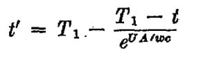
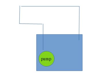
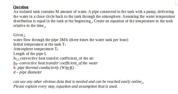
An isolated tank contains M amount of water. A pipe connected to the tank with a pump, delivering the water in a close circle back to the tank through the atmosphere. Assuming the water temperature distribution is equal in the tank at the beginning . Create an equation of the temperature in the tank relative to the time .

Given :
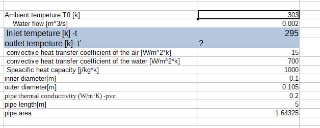
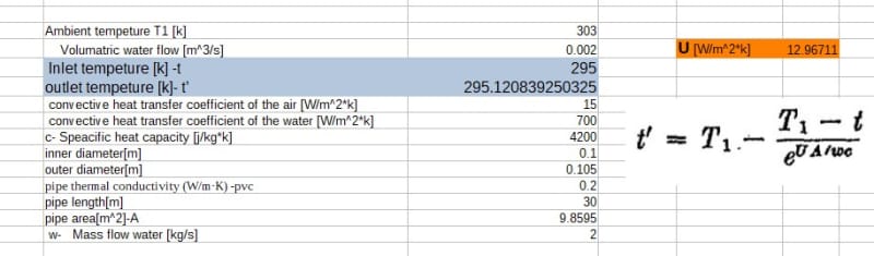
water flow through the pipe 3M/h (three times the water tank per hour)
Initial temperature at the tank T1
Atmosphere temperature T0
Length of the pipe L
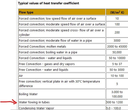
h0 - convective heat transfer coefficient of the air
hW -convective heat transfer coefficient of the water
k- pipe thermal conductivity (W/m·K)
d – pipe diameter

*Can use any other obvious data that is needed and can be reached easily online .
Please explain every step, equation and assumption that is used.


Screenshot_2022-10-30_084840_dg1kt3.jpg


Replies continue below

Recommended for you

Thank you very much for your great posts. Well my team has already have a device to cool down the water. This device consumes an amount of energy /money and also cools down water for an amount that we know already. So this is why I'm asking only about the temperature drop, relative to the time, then we know if it's worth to us to install this device, that might be expensive. Other ways to cool down the water are possible, but this is not what we are testing. Sorry if it wasn't clear from the beginning.

We can locate the pump outside the tank, and also isolate the tank.

@pierreick has uploaded a file with a great scheme that I think very suitable for this case. I just need to go over it again and understand all the variables there .
Thank you again for all your time and advices!
 
I still don't really understand what you're looking for. Cooling the water calculation is quite simple.

to remain steady temp your heat flow from the tank needs to equal it's heat gain from the ambient air and pump losses.

Heat flow into/from a pipe from air flowing around it seems to be anywhere from 10 to 20 W/m2/K.

So work out the length and area of pipe and you have an input.

How much gets absorbed in flowing passed all the roots is more difficult, but assume similar to the pipe maybe.


Remember - More details = better answers
Also: If you get a response it's polite to respond to it.
 
If energy is being added to the water at a greater rate than the cooler can remove it, the tank will continue to heat until it rejects the difference by conduction, convection, or thermal radiation.

If energy is being added to the water at a lesser rate than the cooler can remove it, the tank will continue to cool until it absorbs the difference by conduction, convection, or thermal radiation or a thermostat turns off the cooling system.

The time required doesn't matter if it is a continuous operation.

As I wrote before - you only need to deal with the water before it returns to the tank so you only need the mass-flow and intended steady-state delta-T to determine the cooling requirement.
 
The cooling system is inside the tank, I can't cool the return, unfortunately, so like, if the temperature drops in the tank from 22 to 25, we activate to system for example.
 
You appear to have a different definition of drops and increases to most other people.

I would have normally expected someone to say "...if the temperature INCREASES from 22 to 25, we ...

But if you have a system there now why re asking the question? Just monitor how often the cooler system works in a 24 hour period and that will tell you how much over powered it is.

So if it only works 8 hours in every 24, then a system three times smaller would just about suffice, or maybe 2.5 times to be on the safe side.

Remember - More details = better answers
Also: If you get a response it's polite to respond to it.
 
Sorry if I was misunderstood. The system is not there yet. And we want to know whether it is worth to install it or not, beforehand. That's is why we want to calculate the increase of the temperature.
 
Another way to reject this excess heat of pumping is to install a fountain that sprays the warm tank water into the vapor space of the tank, and let the now cooler water fall back into the tank. Heat of evaporation will be from the warmer water. The pressure in the pump delivery line should be enough to install a spray nozzle on a tee off the delivery line.
 
That's is why we want to calculate the increase of the temperature.

Increase, or decrease, and based on what numerical information you've not provided. We can't read your mind, and you're asking people to numerically evaluate a system for which you provided nothing more than a cartoon. This is not how engineering is done, particularly if you are trying to answer whether a cooling system is effective or not. Your ask for a simple equation that you can crank in the privacy of your computer is not plausible given the dearth of information you've provided.

TTFN (ta ta for now)
I can do absolutely anything. I'm an expert! faq731-376 forum1529 Entire Forum list
 
Hi,
Nobody talks about blow down for this process! Are you aware about water chemistry and salt precipitation over recirculation? Most probably with the fresh make up water to compensate the water sucks by plants and the blow down you may be able to manage the process.
As I wrote earlier, a mass balance should have been the answer.

As I said at the start of this query a student's homework. END for me.

Pierre
 
Well he or she did pretty well stringing us along....

Remember - More details = better answers
Also: If you get a response it's polite to respond to it.
 
Dear guys.
Please let's not be emotional about this thread, I'm learning a lot and since it's the first time I'm posting here I'm learning also how to post my questions. About the homework thing, it's me posting also there, since I needed a formula at the end, I thought it might be useful to give it a try there. After that, for example ,we decided to put the pump outside the tank. I will work on @pierrick file, and see if I can come up with the formula, which obviously won't be 100 precents accurate, but it's enough, thank you again and sorry for the mass
 
I will work on @pierrick file, and see if I can come up with the formula, which obviously won't be 100 precents accurate, but it's enough, thank you again and sorry for the mass

You need a design first, then analyze

TTFN (ta ta for now)
I can do absolutely anything. I'm an expert! faq731-376 forum1529 Entire Forum list
 
Ok , so now i input some data into the formulas to see if it makes sense.

first i used that formula that was uploaded by @pierrick

Screenshot_2022-11-06_162603_xoewvt.jpg


In order to calculate the U- overall heat transfer coefficient. i used that formula:

Screenshot_2022-11-06_163023_ufzvmk.jpg


Now my input for a random system is:(please tell me if you see something unusual)

Screenshot_2022-11-06_163711_htnrpp.jpg


The results that i am getting are not too exciting .The U is between 5 to 10. And then here:

Screenshot_2022-11-06_164540_osgy2x.jpg


w- flow, c -specific heat
The e^(UA/wc) very big so it cancel the right part and we have t'=T1 which means the water heated up to the maximum :/

Please try to flow with me on the idea, i know it is not a usual designing , but this is my part in the project, best regards and thank you
 
I told you that a few posts ago....

But Spec heat capacity of water is about 4200J/ kg/ K

Remember - More details = better answers
Also: If you get a response it's polite to respond to it.
 
Since your cooling medium is air at 30degC, you cannot expect t' to be any less than 33degC or so, which means t from the tank pump has to be > 33degC. That is not what you want, is it? If you want tank temp to be <22degC, you have to find some other cooling medium, or use evaporative cooling with some some low humidity air.
 
@georgeverghese , we have already the cooling system and we know roughly it's capabilities , so we just want to calculate the temperature increase.

Now i think i found the mistake, in the formula, mass flow should be input , not volumetric flow.

Now i am getting an increase of 0.1 degrees on a pipe off 30 meters , does in make sense? sounds too little increase no?

*i changed the volumetric flow to 0.0002[M3/s], (2 liter per seconds seemed like too much for this system). now i am getting an increase of 1 degree .

Screenshot_2022-11-07_040102_hkvmii.jpg
 
So, instead of cooling this water stream, you are now heating it by 0.12degC. Your "pipe cooler" is actually a pipe heater.
By the way, where did you get htc of the water to be 700w/m2/degK ? ; this is usually the inside htc for a regular heat exchanger, not for a crude large dia pipe. It should be a lot lower than 700w/m2/degK. And the plastic pipe, with the low k value for plastic, makes it even worse.
 
Just for the example i have a water tank in 22c, the air outside is 30c , after circulating the water it's temperature increases, i wanted to calculate this increase . Maybe what confuses you is the scheme in the file that says isothermal heating . i just use the calculation from there no need actually to heat the water.

Screenshot_2022-11-07_092050_uzsjno.jpg


I guess you can help me please with this data, i picked something online, probably not the best, if you have another source thank you.**** ok got it with the formula of Nu and Pr its 90
 
Status
Not open for further replies.

Part and Inventory Search

Sponsor