Continue to Site

Eng-Tips is the largest engineering community on the Internet

Intelligent Work Forums for Engineering Professionals

  • Congratulations waross on being selected by the Eng-Tips community for having the most helpful posts in the forums last week. Way to Go!

How to go about plate pry for beam bolted under another beam? (Monorail) 1

Status
Not open for further replies.

JD P.E.

Mechanical
Oct 17, 2021
79
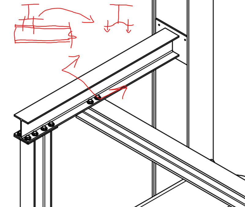
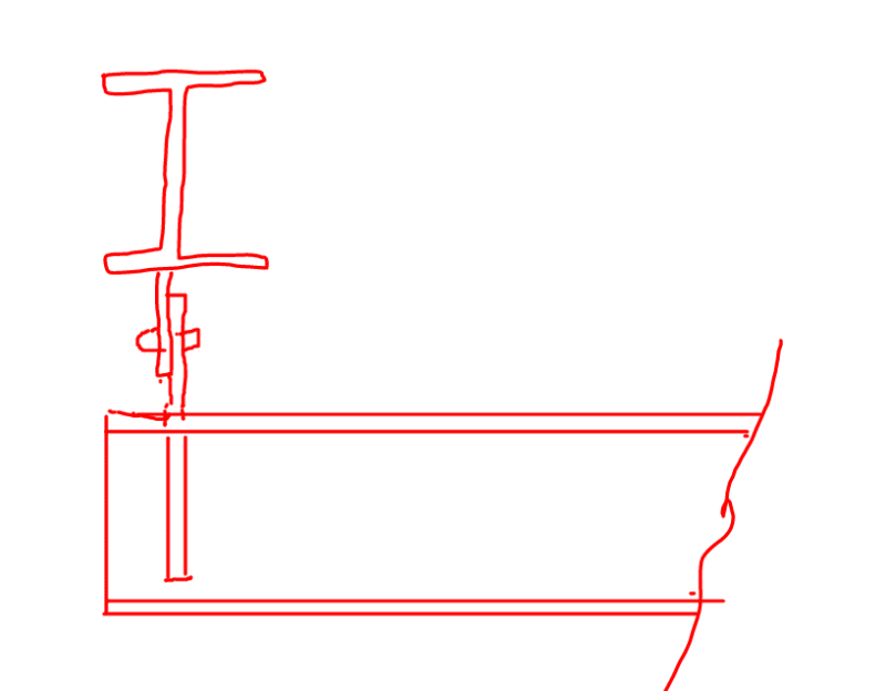
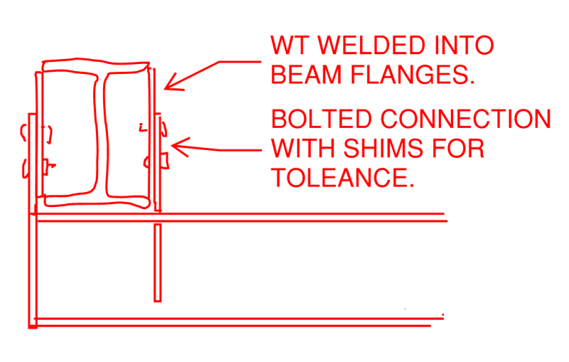
Analyzing monorail for installation in an industrial facility. What is the best practice for checking plate pry on the 2 bolts shown on this connection (Picture attached). There are 4 bolts total, but just checking prying action on the outer 2.

Would you treat it like an angle connection with the weight pulling down at the flange edge of the top beam?
 
 https://files.engineering.com/getfile.aspx?folder=82fae8bc-f1b9-4d2b-86bf-41332c202cc4&file=Forum_Quest.PNG
Replies continue below

Recommended for you

So much happening, beam torsion with flange flex, call me conservative, but I would design for 2 bolts and provide 4.
 
I agree, there is a lot going on. Both the beam and monorail will have web stiffeners to help with flange flex. Will still have to deal with torsion (isn't much, beam is over sized for this application), and whatever prying action there is. The bolts are also oversized, so even with prying I would not be worried. But I need to quantify it.

There are also 2 more bolts on the back side of the beam web you just can't see from this angle.
 
The moment on the bolt due to prying on the bolt would be the moment arm from the edge of the washer to the center of the bolt. Prying on the upper beam web would be reduced by your stiffeners due the load distribution to the web and stiffener. But with 4 stiffeners ( 2 each side) I do not think much actual prying will occur.
 
Maybe I've been a little lax in the past but I have never put an excessive amount of though into such connections. Monorails are pretty harsh on the bottom flange of the monorail even for low loads so I spend far more time doing my due diligence on the monorail bottom flange. Normally a single bolt has enough tension capacity for the expected loads. But I put in 4 and move on. I'd suspect prying forces would be fairly low even without stiffeners due to the thick flanges. (But I haven't done the calculations on this one so if somebody was to call me out on it I'd listen.)
 
If you have 4 bolts then I would check it for prying per AISC 9-10.
Screenshot_m4tmdo.png
 
I don't love the use of a connection prone to prying in a situation that might subject the connection to a fatigue demand. Is there some, practical reason why the connection shown below would be infeasible? Blodgett would approve (at least mechanically).

Note that I know of nothing published that says that there is anything at all wrong with the original scheme in such an application.

C01_dvvp9d.png
 
Or this if there can be no gap between the monorail beam and the girder. Anything really to move the load around in shear rather than plate bending.

C01_fxvfli.png
 
Hey Kootk. Do you really think there is a realistic risk of fatigue in two hot rolled members bolted together like this?

If I was going to be concerned about fatigue surely the welds would be a greater concern? (EG in the cleat shown in your first image.) Though in this case I'm not particularly concerned with fatigue, though maybe I am naive and I should be.

(Some bending of a plate in my mind isn't a terrible fatigue issue. A many moment connection light posts and similar such connections regularly have such bending plate loads.)
 
human909 said:
Do you really think there is a realistic risk of fatigue in two hot rolled members bolted together like this?

I don't have a good enough feel for the numbers here to be able to comment on that with much confidence I'm afraid. My point was really that:

1) I consider it to be a fundamental tenet of good steel detailing that loads should be moved around in plate shear rather than plate flexure whenever possible.

2) When there is prying, there tends to be uncertainty about the amount of flexural stress generated within the connection. And that means uncertainty in establishing the stress ranges at play for fatigue evaluation.

So, if I'm going to use a mechanically poorer detail when mechanically better ones are available to me, I would want a good reason for that. Possible options:

3) Cost if the basic four bolt setup with it's associated, welded stiffeners that OP mentioned is significantly cheaper.

4) Perhaps your are correct and my bolts and welds arrangement is indeed worse than OP's bolts and welds arrangement for fatigue.

As is often the case, I really enjoy kicking around alternate detailing options and discuss their merits. That's the crux of what I've done above.

OP said:
If I was going to be concerned about fatigue surely the welds would be a greater concern? (EG in the cleat shown in your first image.)

OP's solution also has structurally active welds on the stiffeners proposed.

human909 said:
Some bending of a plate in my mind isn't a terrible fatigue issue. A many moment connection light posts and similar such connections regularly have such bending plate loads.

Granted. But, then, I would say that those choices are dictated by the practical necessity of mass construction economics rather than by what is most structurally awesome. Additionally, pole bases usually sit on grout or are gapped. In both cases, you do have plate bending but you do not have prying and its associated uncertainty.

 
Thanks for your reply Kootk. You've given me something to thing about... I'm not completely convinced by your arguments but I respect your knowledge. So I'll have to ponder them some more and maybe crunch some numbers to reassess or reconfirm my stance as my stance isn't base as much on gut feel than thorough engineering.
 
human909 said:
You've given me something to thing about... I'm not completely convinced by your arguments but I respect your knowledge.

I really do not have any serious concern with you detail. I simply thought that I might be able to improve upon it.

A couple of other things, completely unrelated to this thread.

1) Can you come say hi over here. I feel that you may be able to help me with something that is of great interest to me. Really just my sketch at the end.

2) Are you a member of the Pub forum here? I've got some structural bicycle stuff that I'd like to get your input on.
 
@Kootk

1. I think you had that one covered yourself. But I've added my 2cents. I hope it made sense.

2. I haven't stuck my head into the Pub forum until your comment today. I couldn't see anything relating to bicycles so I presume this is a future post?
 
human909 said:
I haven't stuck my head into the Pub forum until your comment today. I couldn't see anything relating to bicycles so I presume this is a future post?

It will be a future post. Two actually:

1) What causes fork shudder with cantilever brakes in general and;

2) What causes / solves speed wobble / shimmy on road bikes (my road bike).

I've decided to attempt to place these threads in the structural forum rather than the pub and see if that gets me into trouble. The conversations will be centered around structural behavior and I'm obviously a real structural engineer. The only oddities are that the questions not pertain to paid work and there's little chance of anyone making use of the threads in the future.

Unfortunately, if I put my threads anywhere other than here, I likely won't hear anything from my favorite/trusted people. Sometimes it is better to ask for forgiveness than permission...
 
Start the thread when you have the chance. The first one I believe is easy to explain and generally has an easy fix. The second one is a complex one as it involves resonance and synchronous excitation feedback from the rider. Easy to explain in hand waving manners much hard to get down to the exact detail.
 
Status
Not open for further replies.

Part and Inventory Search

Sponsor