Continue to Site

Eng-Tips is the largest engineering community on the Internet

Intelligent Work Forums for Engineering Professionals

  • Congratulations waross on being selected by the Eng-Tips community for having the most helpful posts in the forums last week. Way to Go!

Steel Angle Bending/Splitting 1

Status
Not open for further replies.

ryaneng

Structural
Mar 23, 2022
42
Hi all,

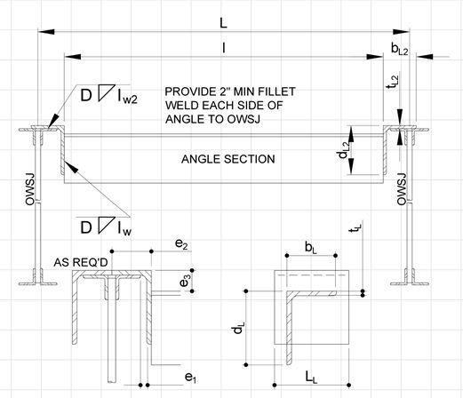
I'm reviewing some drawings from a steel manufacturer for some steel framing around a roof opening in a metal deck roof. The metal frame will rest on OWSJ's, and support the roof deck around the opening. What they've submitted doesn't match our details, but I do think it's a much easier construction, and could work in some situations. Our detail: Their drawing:
My main concern is the point where the flat steel angle portion meets the vertical web of the angle. The flat plate has enough bending capacity without the vertical, but what resistance does the member have to splitting where they join together. I think an easy fix is to simply add in a gusset plate where the vertical starts (or revert completely to our detail), but I think their detail is nice for constructability and I would like to use it in certain low load applications if I can prove it works.

What are your thoughts? Am I missing something, or is there a straightforward check I can complete? Typically when members like this are coped the shear resisting vertical web is what remains...
 
Replies continue below

Recommended for you

I'd be inclined to stick with your original detail. Things I don't like about the alternate:

1) Support reaction is irrevocably eccentric from the shear center of the angles. So torsion until you hit the rectifying cross members which is yucky to deal with analytically.

2) As you've surmised, at higher loads, shear and plate bending will overcome the capacity of the horizontal angle leg. Evaluating this is tricky as well because of the torsion mentioned in #1. How much of that leg is effective in resisting shear?

3) I'm surprised that this saves $$$. I've been under the impression that coping out the heel/fillet area to a flat plate is very expensive. Or maybe they are cutting that part away and leaving only a partial horizontal leg?

4) Hopefully you get paid too much to justify the time that you'll spend trying to save someone else a few pennies.

I agree that the alternate certainly would work for some range of loading. And I'm sure that we could dream up some, rational evaluation procedure if you really feel that it's worth the time to do so.
 
Is splitting really a thing? I generally see their detail in practice.
 
KootK said:
heel/fillet area to a flat plate is very expensive
Would be quick in the shop with a plasma cutter and not too bad in the field with a 7" cut-off wheel. I imagine it is also a lot easier to erect.
 
XR250 said:
I imagine it is also a lot easier to erect.

Why?

XR250 said:
Would be quick in the shop with a plasma cutter and not too bad in the field with a 7" cut-off wheel.

Whenever I've tried to do similar things with other kinds of members, I seem to get spanked for it. Maybe the smallness of the angles alleviates that.
 
KootK said:

In a retrofit, there could be more leeway in being able to slip the angles in with 6" of vertical leg removed.
 
XR250 said:
In a retrofit, there could be more leeway in being able to slip the angles in with 6" of vertical leg removed.

Oh come on... that's only 2" more than than would be "vertical angle free" with the mechanically better detail. In two decades of practicing, I can't say that I've ever encountered a situation where that would have mattered. If anything, it would be more about the vertical legs of the clips running the other way and I feel that the odds of those being deal breakers is equally remote.
 
Thanks for the initial thoughts. I do think their detail is easier to fabricate, though not really any easier or harder to install (unless it's a retrofit like XR250 mentioned).

XR250 said:
Is splitting really a thing? I generally see their detail in practice.

I guess splitting isn't a technical term for the stresses at that location, but I do think that is a real experience for the member. There's a sharp change in stiffness properties and that would try to pull apart the horizontal and vertical legs at the extreme corner.

KootK said:
4) Hopefully you get paid too much to justify the time that you'll spend trying to save someone else a few pennies.

Probably paid too much to spend a lot of time on one single job, but if I can improve the detailing on many jobs (and keep the steel guys happy) I believe that's good for business.
 
For light loading the proposed one is workable and likely less costly. The load capacity (reaction x the eccentricity of the reaction) is limited by the capacity of the leg thickness x the width of the angle. Your detail can accommodate loads and is limited the thickness of the supporting clip x the length of the supporting clip which can be 6" or 8" or more. Your approach is so common that I've written a couple of SMath programs because I encounter it so often. The programs stipulate the supporting eccentricity which I usually limit to 1" and also if the support angle if fully welded the support. One the support is pinned for the eccentricity and the other the support is fixed, which 'halfs' the eccentricity. I'll dig up a copy of the SMath and post it later... up to my neck in 'gators, currently.

One of the programs determines the max capacity of the L based on max UDL for section capacity... another of the programs does the same for a C Section.

Rather than think climate change and the corona virus as science, think of it as the wrath of God. Do you feel any better?

-Dik
 
ryaneng said:
I guess splitting isn't a technical term for the stresses at that location, but I do think that is a real experience for the member. There's a sharp change in stiffness properties and that would try to pull apart the horizontal and vertical legs at the extreme corner.

I got your drift even if "splitting" might not have been the best descriptor. Maybe "tearing" at a stress concertation that you sure hope is yielding rather than splitting. Your spot on with the basic mechanics of it though.

ryaneng said:
Probably paid too much to spend a lot of time on one single job, but if I can improve the detailing on many jobs (and keep the steel guys happy) I believe that's good for business.

I don't see that making much of a business development impact unless the fabricator is actually is your client here or in the future. I can't see a contractor objecting to using you as the EOR for a new project just because a steel fabricator doesn't like that you insisted on doing what is commonly done on some dinky roof opening frames. Steel supply contracts are way to cost driven for that to be the case.

dik said:
The load capacity (reaction x the eccentricity of the reaction) is limited by the capacity of the leg thickness x the width of the angle.

I suspect that it's really quite a bit worse than that. I'll check it out in the Smath.

Obviously, the fabricator preferred setup has some capacity and I'd be happy to use it for ceiling fans etc. That said, if I had it in my standard details, I'd worry that it would be just a matter of time before I found that setup under a moderately sized RTU. I'd need three versions:

1) Channels for the big stuff.

2) Angles without the clips for the truly little stuff.

3) Angles with the clips for the in between stuff.

That would be getting too fancy / error prone for my liking. If I were to have angles w/o clips on the roster, I'd need to be confident that the suitably replaced all instances of angles w/clips.

 
KootK said:
Oh come on... that's only 2" more than than would be "vertical angle free" with the mechanically better detail. In two decades of practicing, I can't say that I've ever encountered a situation where that would have mattered. If anything, it would be more about the vertical legs of the clips running the other way and I feel that the odds of those being deal breakers is equally remote.

Looks like I got your panties in a wad :)

These are overhead welds (in retrofits) - which suck in general. I would argue without the vertical leg of your clip angle in the way, it is an easier weld.
 
KootK... what I do is calc the section properties of the supporting angle or channel and calculate the max UDL for the span and take 1/2 the total UDL as the reaction. I then calculate the moment based on the eccentricity of the support condition to determine the moment in the 'clip angle' at the end. Using the clip angle thickness and the length, I calculate the moment resistance of the clip angle... I can override the max reaction calculated to imput a real load, change the eccentricity, and change the length and thickness of the clip angle to suit... I do the same thing with C Sections and end clip angle supports... I can even change the weld size or electrodes... I may have a dozen of these support conditions in a week. If the clip angle is fixed at the support, I basically half the eccentricity, assuming it is fixed at each end. I append the summary printout for several conditions to a single project file... no rocket science...

Often loads aren't specified, except based on UDL max for the span... sometimes they spec angles and other times they spec channels. I forgot to add that I can also change the grade of steel for the main member or for the clips. I don't check deflections.

Rather than think climate change and the corona virus as science, think of it as the wrath of God. Do you feel any better?

-Dik
 
This is a schematic...

Clipboard01_g4ypex.jpg


Rather than think climate change and the corona virus as science, think of it as the wrath of God. Do you feel any better?

-Dik
 
Thanks for the diagram Dik. Do you consider it any differently if it's just the horizontal piece of an angle that extends over the OWSJ, without a discrete plate where it transitions to the full angle?

I can calc the moment in the flat plate based on the UDL and check it works for bending as a plate, I'm more interested in how it behaves (and what I can count on) when the vertical leg is reintroduced.

 
As I noted earlier, "For light loading the proposed one is workable and likely less costly. The load capacity (reaction x the eccentricity of the reaction) is limited by the capacity of the leg thickness x the width of the angle. Your detail can accommodate loads and is limited the thickness of the supporting clip x the length of the supporting clip which can be 6" or 8" or more." for light loading removal of part of the leg of the angle can accommodate light loads. If they are for trimming out openings in a roof and not used for supporting significant loads, they are likely much less costly.

Rather than think climate change and the corona virus as science, think of it as the wrath of God. Do you feel any better?

-Dik
 
I would be hard pressed to criticize the manufacturer's detail, as I have detailed opening frames that way for many years.
 
XR250 said:
These are overhead welds (in retrofits) - which suck in general. I would argue without the vertical leg of your clip angle in the way, it is an easier weld.

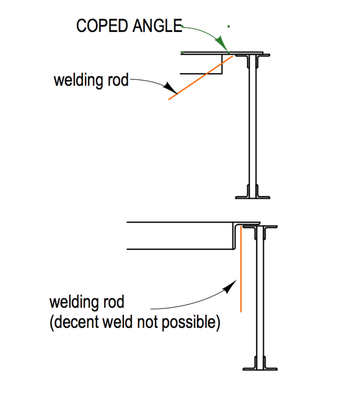
Speaking of retrofits I have been doing a few of these this year (as the metal sub) due to HVAC upgrading in schools and the like as a result of Covid. Every time I cut open the roof deck to weld the angles to the joists from above as I can't really see a CWB position approved way to access that weld otherwise (like the one Dik shows in his schematic just above).

Also, every time, the roofer gets up in arms that I'm cutting outside the curb extents to perform that weld and say they never see that done. But to date, not one of them has been able to tell me how that weld gets done in a retrofit without opening the roof deck. What typically happens in a retrofit in your experience? How does that weld get performed (from angle that sits on top of OWSJ to the OWSJ at the sides) or do we think that weld just DOES NOT get done in a lot of cases (and angles just hang there) and that's why the roofers are saying they never cut open the deck?
 
Yes I agree if the EOR allows welds there (the thickness of top chord can be a bit of a problem for small angles so not all are agreeable to this). But I'm talking about welds on-top of the OWSJ like Dik's sheet, which is all I have been seeing and EOR's have been unrelenting about doing something different. How does this get done without opening the deck? I just need to know I'm not crazy!

Capture_tiefm7.jpg
 
XR250 said:
Looks like I got your panties in a wad :)

Please... when it comes to structural engineering, I know no panties but wadded panties.

XR250 said:
These are overhead welds (in retrofits) - which suck in general. I would argue without the vertical leg of your clip angle in the way, it is an easier weld.

Okay, I see what you're getting at now and I agree. When you'd mentioned the 6" absence of the angle leg parallels to the clip, I thought you were trying to clear existing services or something which sounded ridonculous.

I've not done angle frames for retrofits. When I've done retrofits, I've used a detail using two piece channels that get lap spliced and tried to slot the clips in through the deck flutes without having to lift the deck at all. It's complex and never seems to work out as well as I want it to. My version of your weld happens on the far side of the OWSJ chord with this setup, however, which is why weld access has not been an issue for me.

Can you describe how your retrofit system works in more detail? Do you assemble the frame in the field, angle by angle? Do you attempt to slot the coped, horizontal angle leg into the deck flutes or just lift the deck locally and put it wherever it needs to be? With a single piece angle, I feel like you'd need to come into a flute skewed at one end and then swing the other end into place, lifting the deck as you go.

 
Status
Not open for further replies.

Part and Inventory Search

Sponsor