Sem D220 15 Mar 19 22:16 said:
What do you suggest to do for simulation of a UAME of an inspected feature as part of position RFS or center plane/axis orientation RFS control?
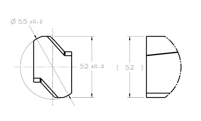
As for a physical gauge, I would really defer to someone with more experience in gauging - however I do know that this is one of the main reasons that gauges for RFS position are much more expensive. The first thing that comes to mind though is an expanding pin - this could be utilized to simulate the UAME of an RMB primary datum feature and could touch/constrain other features and DOF
as long as it was expanded within the primary datum feature first. Another could be a free floating expanding pin which is inserted and expanded within a hole and does not contact any other features - this could be utilized to find the size of the UAME (or a series of solid plug/pin gauge could be inserted until one is found which just fits - this would provide a similar function). As far as how to utilize this simulated UAME to gauge RFS position I would let someone more experienced than I answer that.
Sem D220 15 Mar 19 22:16 said:
Without establishing the DRF the tolerance zone is undefined. How do you suggest to verify those tolerances without limiting the degrees of freedom of the part?
UAME =/= tolerance zone. The UAME must fall within the established tolerance zone - or in the case of a primary datum feature, it establishes the DRF from which other features are derived.
Sem D220 15 Mar 19 22:16 said:
If my personal opinion matters, I still say that the most rational way to approach this is to simply follow paragraph 4.11.4 for every case where a UAME should be simulated.
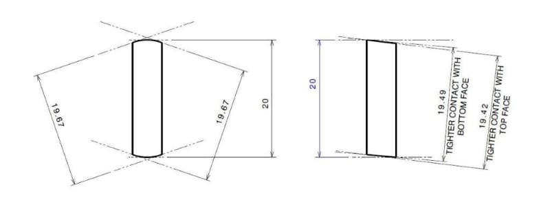
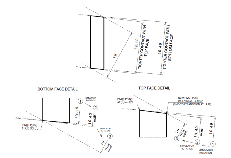
I do not see how this helps clarify matters considering the additional term "maximum possible contact" is still not defined within the bounds of the standard. As far as I'm concerned, the 3 points of contact is just a result of maximum expansion/contraction/progression of the boundary to reach its largest (for an internal feature) or smallest (for an external feature) size. Even if 3 points of contact can be established before then (in your example - the 19.49 boundary) it is not the UAME unless it has reached its smallest size (the 19.42 boundary).
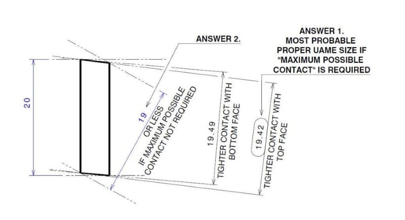
In regards to your two features, for the second one I agree with pmarc that the correct UAME is unambiguously 19.42 - your alternative "19 or less" is not valid. If you consider contraction of the boundary as it progresses towards its minimum separation, 19.42 is the only solution - to achieve a smaller boundary (your "19 or less") it is no longer only contracting but also rotating arbitrarily away from the surfaces being simulated.* Conversely this would also happen if you were starting contraction with the part at an excessive angle such that it closed down on the longer 2x faces instead of the shorter 2x faces in question.
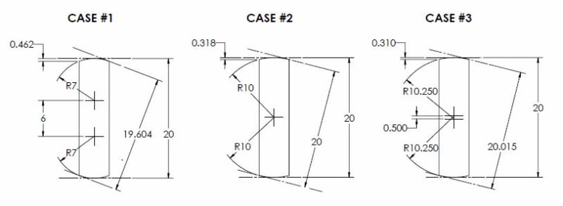
In regards to your first figure, I was intrigued as to why I did not see that on my initial, admittedly quick, look at the geometry. It looks like with features of a high length to width ratio as you have shown, with relatively loose tolerances (not unreasonably so - but definitely not very tight) on the size/form an unstable situation could arise. If I have some time I might come up with a formula to show the relationship, but in the meantime the below figure shows that in order to create the situation you showed it requires the center of the arcs which make up the barrel shape to be at some separation from each other, which also requires a relatively small radius on each side resulting in a relatively large size/form deviation. If these arcs are changed so that their centers are coincident then the feature essentially now becomes round and there is no minimum as the separation becomes the diameter and is the same at every point. If these arc centers cross the centerline then there is now a minimum at the apex of each arc and the feature now becomes "well behaved" - as the size/form tolerance gets tighter this would only become more true. I don't know how often one might encounter this as it requires a specific set of conditions, and I do not know exactly how this would be handled in regards to establishing a UAME - however I do not think it is perfectly analogous to your OP example as they are not "unstable" in the same sense - ie: I think you would find that if you contracted a physical boundary about my case #2 below I think you would find it relatively stable, despite having no minimum. The same could not be said for your OP with offset planar features.
Note the difference in the size/form deviation of each feature (.462 / .318 / .310 respectively). As I stated if this is minimized by a tighter tolerance, this instability and lack of defined singular minimum disappears.
*I know I stated in my reply (15 Mar 19 18:19) that theoretically these boundaries would coexist with the surface and maybe downplayed the physical realities, based on pmarc's replies and thinking about it some more I think I was on the right track initially by focusing on the physical realities of simulation.
**Edit - made the figure more readable, I realize that the dimensions may have been hard to read.