Tek-Tips is the largest IT community on the Internet today!

Members share and learn making Tek-Tips Forums the best source of peer-reviewed technical information on the Internet!

  • Congratulations MintJulep on being selected by the Eng-Tips community for having the most helpful posts in the forums last week. Way to Go!

factors to be considered for vessels in cyclic service

YuJie_PV

Mechanical
Joined
Jan 19, 2017
Messages
159
Location
CN
hi, all,

my company had a training on vessels under cyclic service.
it's advised to consider the following factors in case of fatigue analysis to increase fatigue life:
  1. Vessels to be PWHT(For CS)
  2. All welds be full penetration
  3. Integral construction
  4. Avoid slip on flanges
  5. Avoid leg support
  6. Avoid peaking at Category A joints
i wonder if they are mandatory per ASME VIII-2? i look through the rules in Code, and can't find any basis.
what do you think of these factors?

Thanks in advance
 
That’s not a bad list. I’m curious to hear your thoughts on the logic behind each of those items on the list. I have my thoughts but I’d like to hear your thoughts first.
 
@TGS4,thanks for reply.

my two cents:

1. Vessels to be PWHT(For CS)
i think it's not mandated in both Div.1&Div.2 of Section VIII, despite of that, i think the reduced residual stress and improved toughness of material, as a result of PWHT (for CS), could benefit the increase of fatigue life. i don't quite understand the rationale underneath it, i guess the stress amplitude of a location in interest in a PWHTed vessel would be significantly decreased than that in the vessel kept being as-welded, under the same operating condition.

2. All welds be full penetration
not mandatory.
i think partial penetration creates sharp corners/edges, especially in the gaps (e.g. the nozzle neck and shell) where could not be visually seen by eyes, thus hard to achieve a smooth contour of weld. it's these locations hidden somewhere that are prone to crack under cyclic loads.
it's a recommended good practice.
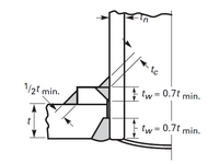
1752467768281.png

3. Integral construction
Not mandatory.
similar logic as 2. the construction not integral can't avoid sharp corners/edges (e.g. between the repad and shell) . it's these locations where are prone to crack under cyclic loads.

it's a recommended good practice.

4. Avoid slip on flanges
Not mandatory,
but recommended.
Slip-on is not integral construction.


5. Avoid leg support
Not mandatory.
typically the wear plate attached to head shall be used for leg support, which isn't a integral construction. Maybe there is only one solution, SKIRT, which could achieve a full penetration between support and shell. it's not practical to use a skirt on those common vertical vessels except for tall towers.
i think the factor could be disregarded if not for towers.

6. Avoid peaking at Category A joints
Not mandatory.
para. 5.5.1.7 in Div.2 states: " If a fatigue analysis is required, the effects of joint alignment (see 6.1.6.1) and weld peaking (see 6.1.6.3) in
shells and heads shall be considered
in the determination of the applicable stresses."
the clause seems implying that the weld peaking shall be considered in fatigue analysis rather than be avoided. i look through the VIII-2 and couldn't figure out how to consider the weld peaking in analysis. maybe just dictate a max. limit for the peaking in fabrication drawing, similar as the misalignment of joint, and perform the FEA as usual. when it comes to reality, but how to determine the limit? it seems tricky.
in my experience, no engineer considers the peaking limit of weld either in the fabrication drawing or in the FEA report. it puzzles me.


above are my thoughts on these factor, please comment.

actually, my colleague also advised some other factor for cyclic service, such as main weld joint ground flush, material to be normalized, material to be fine grained, which i am clear about, have no confusion.

Any reply appreciated, thanks.
 
  1. Avoid lifting lugs, always
  2. Fillet weld shall be with a radius
  3. No pads for attachments
  4. Butt welds shall be flush.
  5. UT before cut the plate to the hole for a nozzle. PT in bevel of the hole.
  6. Full penetration welds
  7. Pressure test UG-99(c)
  8. Long welding neck flange instead of reinforcing pads
  9. Preheat in all welds. PWHT as per CODE.
  10. RT 100% in longitudinal weld. Spot in circumferential weld in tall towers
  11. PT 100% in all welds.
    Fatigue cracks at pressure vessel welds are typically located at the toe of a weld. For as‐welded and weld joints subject to post weld heat treatment, the expected orientation of a fatigue crack is along the weld toe in the through‐thickness direction, and the structural stress normal to the expected crack is the stress measure used to correlate fatigue life data. For fillet welded components, fatigue cracking may occur at the toe of the fillet weld or the weld throat, and both locations shall be considered in the assessment. It is difficult to accurately predict fatigue life at the weld throat due to variability in throat dimension, which is a function of the depth of the weld penetration. It is recommended to perform sensitivity analysis where the weld throat dimension is varied.

The above must be applied with good engineering judgment.
Some comments are according to ASME BPVC 2023. It is possible that changes in the 2025 edition may occur.
 
@YuJie_PV - most of your explanations seem logical except:
1. The rationale to require PWHT is to reduce the mean stress (note that the Structural Stress Method for the Fatigue of Welds has a mean stress correction factor). PWHT does not impact the stress amplitude at all.
2. Reasonable
3. Reasonable
4. Reasonable
5. For localized stresses, I generally agree with your rationale. On one hand legs can provide very good flexibility. On the other hand, many skirt attachments are created from fillet welds with the root being uninspectable. That can also be problematic if the driver for the fatigue is thermal stresses.
6. The weld peaking can be very important for cyclic pressures - it is critical for vessel such as those used in the Pressure-Swing Adsorption use.
 
My 2 cents on @r6155 's list:
1. I agree that pressure-boundary lifting lugs that remain during service are not good practice. Leaving lifting lugs on skirt base rings are completely fine.
2. If you mean the fillet cap on a full-penetration weld, I agree that these should be ground or machined to a smooth radius.
3. 100% agree
4. Agree
5. I've never hear of this as a fatigue good-practice. What's the theory on this?
6. 100% agree
7. I agree that test pressures should be maximized to take advantage of the beneficial results of localized yielding and the resulting compressive surface stresses.
8. Agreed
9. In the case of vessels in cyclic service, I would generally recommend PWHT in excess of the Code requirements - I would recommend it in all cases - based on the explanation I left in my response to @YuJie_PV #1.
10/11. I would recommend 100% VT, 100% volumetric (RT or UT), and 100% MT/PT on welds subject to cyclic service. Otherwise, the FSRF will be higher.
 
@TGS4,@r6155, thanks for all your clarification. i've learned so much from those.

Regarding PWHT's impact on fatigue life, I just accidentally come across an explanation from TWI, seeming a reputable organization.

Does PWHT increase the fatigue strength of steel welded joints?
There is no increase in fatigue strength for welded joints subjected to entirely tensile applied loading cycles. If the applied loading is partly or wholly compressive, PWHT will be beneficial, provided residual stresses are fully relieved. The relevant UK standard BS7608:1993 'Code of practice for fatigue design and assessment of steel structures' allows 40% of the compressive part of the cyclic stress range to be ignored in estimating the fatigue design life. However, there is a requirement to demonstrate that stress relief is effective, for example by measuring the residual stress adjacent to the joint of interest after PWHT.
i don't quite understand their logic. Based on TGS4's clarification, i think there is a residual stress in vessel if no PWHT , which is superimposed on the stress amplitude due to cyclic loading, thus increase the mean stress (where the residual stress is tensile) and further affect the fatigue life. Residual stress is always there, no matter if the applied loading is tensile or compressive.
it doesn't make sense with the explanation of TWI, or am i missing something?
Please comment.
Thanks in advance.
 
Clause 5.5.2(a) includes design features that are not recommended when designing vessels for cyclic service.
(a) the use of nonintegral construction, such as pad type reinforcements or of fillet welded attachments.
(b) the use of pipe threaded connections, particularly for diameters greater than 70 mm (2.75 in.)
(c) the use of stud bolted attachments
(d) the use of partial penetration welds
(e) major thickness changes between adjacent members
(f) attachments and nozzles in the knuckle region of formed heads
 
Be care.
BS 7608.2015
1.2 This BS is not applicable to unfired pressure vessels (See BS en 13445)
 
@IdanPV, Thanks for those addition. i find the terms used in 5.5.2(a) is confusing,.
(c) the use of stud bolted attachments
"stud bolted attachment"? shall manhole/handhole be covered? or is it referring to studding outlet type flange?
(e) major thickness changes between adjacent members
is it referring to the thickness change between adjacent shell courses? how much is the value constituting "major thickness change"?
it's confusing.

Thanks again.;

@r6155, respectfully disagree, the explanation seems a description of physics, and the law of physics is universal。

thanks so much.
 

Part and Inventory Search

Sponsor

Back
Top