Continue to Site

Eng-Tips is the largest engineering community on the Internet

Intelligent Work Forums for Engineering Professionals

  • Congratulations cowski on being selected by the Eng-Tips community for having the most helpful posts in the forums last week. Way to Go!

Existing PEMB - Multi Column Removal/Jack Truss

BuildWithSteel

Structural
Apr 27, 2025
1
Modifying PEMB- am interested to hear what solutions others might have gone with in my situation, even if I end up regretting the final solution I landed on.

Multispan, existing pre-engineered metal building- 4 bays, 54’ wide, PEMB bents at 25’ on center- total building length about 350’ long. Interior columns are Pipe 8”- couldn’t say for certain wall thickness at time of design other than tapping the column to hear the tone of “ping” it made- it sounded thin LOL. I wouldn’t have actually trusted that “test” if I had actually planned on somehow attaching to existing columns. Exterior columns are typical built up tapered plate columns.

Assumed interior columns are pinned top and bottom for only gravity based off of light, simple beam over column cap plate connections and base plate configuration- bolts from cap plate to PEMB bent was only 1/2” diameter as an example.

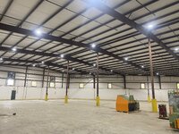
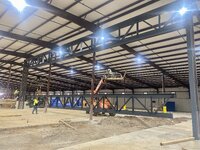
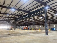
I needed to remove 2 of the interior ridge line columns for a 75’ clear span.

Attached photos was my solution- reinforced/enlarged the existing footings each end, 2-new pairs of columns added each end, sandwiched existing column line with a trusses braced to eachother each side as a jack beam/truss, existing columns cut out once all connections made- no shoring was needed this route. It’s not a fancy solution- one that you can look at and logically see exactly how it works. Possibly a bit overdone.

What might have you done differently in situation?
 

Attachments

  • IMG_5795.jpeg
    IMG_5795.jpeg
    2.5 MB · Views: 92
  • IMG_6042.jpeg
    IMG_6042.jpeg
    2.8 MB · Views: 90
  • IMG_6072.jpeg
    IMG_6072.jpeg
    2.7 MB · Views: 89
Replies continue below

Recommended for you

Actually looks simple and reasonably conservative to me. I do not know how much wind load you have where you are at, but I assume you checked the truss for LTB of the lower chord for wind uplift. I did not see any lower chord lateral braces at the frame lines but not needed if the lower chords can span 75' with no lateral bracing. I assume your top chord unbraced length is 25'

Also it does look reasonable to assume the interior columns are pin-pin. Most PEMBs are designed that way even though there are no guarantees and your baseplates and top plates look like pinned.
 
Is this a new approach to a "humble brag"? Post something clever you have done and ask others how they would have done it differently? ( :LOL: joking)

I agree with Ron. This seems like a good solution. The best choice here IMO was to design an approach that didn't need shoring. That makes life signifcantly easier for the guys on site. And saves money even if you end up with more steel than a non shored outcome.

The truss seems to be on the heavy side. But maybe you needed that for the deflection or LTB. LTB could have been restrained by the rafters (fly braces for uplift) but that would start making things more complicated. You seemed to have adopted, clever, simple but not necessary weight efficient. But sometimes that is the best approach.

If I was designing that truss I likely wouldn't have back to back angles. You are increasing the welding significantly and likely making painting harder. I would have chosen H-sections for my cord and angle or HSS for the web member depending on loads.

But that is just my initial thoughts and comments there are many was to skin this cat. Your way seems very effective.
 
Very nicely done. I'm a PEMB guy. The 8" pipe columns are schedule 40 std 8" pipe. Round HSS is not readily available on the market despite being listed in the steel manual. also the pipe column was definitely designed as pinned-pinned.

I jacked out a column supporting (2) 5 ton cranes on either side. Designed it for the loads and held a very stringent deflection. They installed the beam and then cut the column and started letting it down. It should have only gone down 3/8" even with crane loads but it went down further. I had them stop and weld the top of the column back up to the top. Ended up reinforcing my beam to be many times stiffer than what my numbers said it should be and that has worked great. Long story short, no reason to get cute with this type of thing. If you think your solution is a bit overdesigned, it may not be.
 
The stiffness of the truss and columns may attract some lateral load to the interior of the building and away from the cable or rod braces at each end. I would analyze whatever stiffness it has and make sure the strut purlins in the area can take any redistributed loads. You may have done this.
 
The stiffness of the truss and columns may attract some lateral load to the interior of the building and away from the cable or rod braces at each end. I would analyze whatever stiffness it has and make sure the strut purlins in the area can take any redistributed loads. You may have done this.
I've been meaning to post the same thing for a while. Though the rod bracing isn't really relevant unless we are talking different directions.

Portal frames of this size can often move 100mm+ in the direction of the portal framing in ultimate cases. The previous columns were pinned top and bottom and would sway with the building. This setup is mostly a rigid connection to the footing.

Though I notice you have forgone a final diagonal to the ground. Maybe you did this for this very reason and this allows enough flex in the channels. That is certainly my approach.
 
I want to add something about the flexibility of PEMB structures--They're much more rigid than you think in the direction perpendicular to the rigid frames due to an abundance of redundancy. Hypothetically, wind load travels from the top of wind columns through strut purlins until it hits the diagonal bracing, then the diagonal braces, rafters and additional strut purlins form a truss to provide a load path to the ground. These are always designed by PEMB manufacturers as idealized trusses with all connections pinned.
1746221114200.png
In reality, in order for the building to move in that direction, every purlin would have to move in that direction and each of them provides a small moment resistance to that movement. Where flange braces are provided you have even more resistance to that movement. This redundancy is not taken into account in their design.
1746221255372.png
Next the diaphragm capacity of the roof sheeting is neglected but still exists. Even for PEMB structures with deck roofs, that capacity is ignored and x-bracing will be provided.

There are plenty of reasons to hate PEMBs, as this sub reminds me every few months. This just isn't one of those areas.

All this is to say, that I wouldn't worry too much about load from the roof bracing system getting into this truss support. Also, how would you calculate the true stiffness of the PEMB system? We can't even calculate it.
 
The wall rod bracing is about 2 bays past the portal. The rods look loose in the picture. If they are, I would snug the roof and wall rods to minimize lateral movement before the rods tighten from the movement. If the wall panels are capable of diaphragm action, they are probably what are doing the work at the sidewall anyway
 

Part and Inventory Search

Sponsor