Tek-Tips is the largest IT community on the Internet today!

Members share and learn making Tek-Tips Forums the best source of peer-reviewed technical information on the Internet!

  • Congratulations cowski on being selected by the Eng-Tips community for having the most helpful posts in the forums last week. Way to Go!

Eccentric Shear Connection 6

Status
Not open for further replies.

MegaStructures

Structural
Joined
Sep 26, 2019
Messages
376
Location
US
What additional failure modes to be checked for an eccentric skewed shear tab compared to a typical orthogonal shear tab. The shear connection supports high axial load as well as vertical shear and connects to a column flange.

I believe the only differences should be as follows
1) global analysis offsets need to be considered which increase torsion in the supporting column
2) flange bending no longer follows the definition of J10.1 of the AISCM, instead the flange should be checked as a cantilever plate with infinite length per chapter 8 of Roarks. ASD safety factor of 1.67 still to be used for tensile yielding of the flange
3) The weld from shear tab to column will be analyzed slightly different to account for the difference in weld geometry

*Are there any other failure modes to consider in this connection not covered here?
*As a general question how does AISC control certain special cases like this where an approved code equation cannot be used? Is there a general blanket acceptance from the code that allows other analysis procedures per the EOR's discretion?
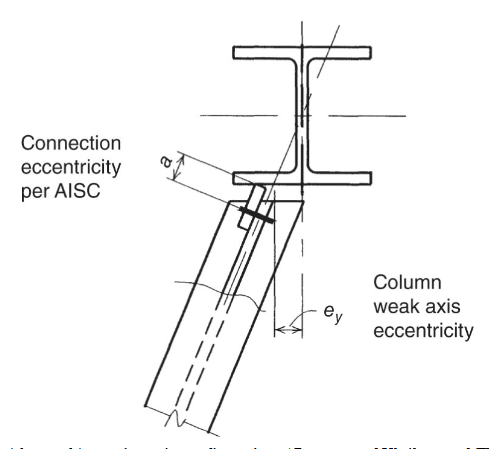
skewed_tab_lytxi8.png


Thanks
 
What I would do - 1) align the line of action with the center line of the shear tab; 2) weld the shear tab using cjp/pjp; 3) add stiffener(s) to the flange.
 
The shear tab can’t be moved and AISC has pre qualified weld details for the purposes of skewed shear tabs in chapter 10 of the newest manual. What would you base adding stiffeners to the flange off of? Adding stiffeners through a large project would be costly, so I feel like it should be proven that the stiffeners are needed.
 
So you are good to go. I wouldn't walk under it though :)
 
retired13 said:
weld the shear tab using cjp/pjp

CJP is a dirty word where I come from, to be used only when required.

I don't think much changes for the design of the shear tab. Going square into the column flange at centerline, you could assume the column is rigid and let that deal with your connection eccentricity. The column flange will be more flexible and you should design your bolt group to deal with the eccentricity.

My preference here would be to use a skewed end plate - fillet welds to beam web, bolt to column flange.
 
retired13 I’m not opposed to using a stiffener plate for the column, but I’m looking for a way to quantify the need for one.

CANPRO I would agree that not much changes as far as the shear tab itself is concerned. I have read a couple papers on skewed shear tabs and they all suggest the only difference in design is the weld strength. I will post the references when I’m back at my computer. An end plate would be a good idea, but it will be difficult to do a wholesale change in the detail now if not needed. An end plate would still cause eccentricity as well.
 
1) No torsion. Torsion is twisting.
2) The code just says eccentricity must be accounted for.
3) The shear tab is not different. The shear tab is checked the exact same way as always.

You may consider connecting to the center of the flange, similar to a standard connection, where eccentricities are neglected.
 
RPMG you are correct there is no torsion being added to the column. I was considering the force components multiplied by their moment arms, but of course they would cancel each other out. Of course should just look at the nice line going through the center of the column :)

Now what say you about the local strength of the flange?
 
Ideas for improvement:

1. Use a bent plate shear tab.
2. Put the shear tab on the opposite side of beam web as shown.
3. Use a flange stiffener if you're worried about the column.
4. Use an endplate detail.
 
The shear connection supports high axial load as well as vertical shear

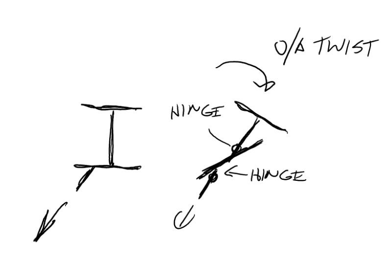
If it has high axial load then in my mind its the wrong kind of connection. I'd have no qualms about high shear load connecting like that, but with axial load there is no real load path except for flange and web bending. I believe there will be a torsion resulting from the axial load acting on the flange, flange and cleat want to straighten under axial load. This will cause twist of the cross section. Sure the resultant is through the centroid of the column, but this doesn't mean you can ignore the local effects and the torturous load path to get the load to the centroid.

What would I do, connect to the flanges of the beam potentially, but definitely create stiffeners behind the column flange to actually transfer the load in a symmetric manner to the column as a whole.


EDIT from some of the other replies I'm not sure if they are picking up on the high axial load aspect, you're calling it a shear tab after all and these are predominantly used for shear only connections to the webs of members
 
In my mind this is what I was meaning regarding the twist with no stiffening to take the load to where it wants to go:-
Annotation_2020-02-15_132541_gle8oz.png
 
Agent66 that was my exact concern with the flange strength, though I was picturing only half of the flange bending, like a cantilevered column supported at the web. I will have to do some thinking on how to prove what load that action will occur. Obviously a portion of the web would have to yield near the flange.

Edit: yes, maybe I should call them knife plates. The geometry of the structure is such that the beams act as horizontal bracing for the MLFRS.
 
Agree with @Agent666: if axial load dominates, this is the wrong type of connection and any "how to I analyze the failure modes of _____" is a waste of resource. Go with connection better suited to axial load or make darn sure that the tab goes above and beyond handling the load direction it is not specifically designed for. Shear tabs can take some axial load, but you need to understand the research behind the connection that has suggested issues with buckling failure and support conditions.
 
MegaStructures said:
I would agree that not much changes...only difference in design is the weld strength. An end plate would be a good idea, but it will be difficult to do a wholesale change in the detail now if not needed. An end plate would still cause eccentricity as well.

The change in weld strength is because you're still specifying the leg size of the weld, but because of the skew, the effective throat changes. Depending on the angle of your skew, the weld may be considered a PPJ and not a fillet weld. If the angle of the beam and column flange is under 30deg you shouldn't count on any strength for the inside weld - in this case you either a one-sided fillet or one-sided PPJ load axially, which isn't a good idea.

Agent666 said:
What would I do, connect to the flanges of the beam potentially, but definitely create stiffeners behind the column flange to actually transfer the load in a symmetric manner to the column as a whole...from some of the other replies I'm not sure if they are picking up on the high axial load aspect, you're calling it a shear tab after all and these are predominantly used for shear only connections to the webs of members

Agent666, I did miss that it was loaded axially. I agree with you assesment of the local flange bending. Stiffeners will likely be required unless the load isn't that high and the columns are really stocky. Be careful using full-depth stiffeners in the column, you really have to be aware of what is framing around and below that location - you can block erection access quickly.

I was also wondering if the flanges of the beam would need to be engaged. I recall you commenting a few times how in New Zealand the building designer also designs the connections. Looks like OP is in the US and likely is doing delegated design work. Connecting the flanges of the beam to the column would need EOR approval unless they were already accounting for that fixity - and if they were, then they should have specified a moment value.

I'd be looking to make a heavy endplate work. But it really depends on the beam and column section, geometry, and loads. Any chance we can get a sketch and loads?

MegaStructures said:
As a general question how does AISC control certain special cases like this where an approved code equation cannot be used? Is there a general blanket acceptance from the code that allows other analysis procedures per the EOR's discretion?

I'm in Canada, so not sure how AISC handles it. Not everything falls into a code equation. Sometimes you have to go to another source (Roarks, Blodgett, FEA, etc). Nothing wrong with that as long as you stay rational, conservative, and stay with the spirit of the code (safety factors/material resistance factors). For me thats my favorite part of connection design.


Column W16x100
Beam W12x50
Axial Force 35 kip

The shear tab itself has sufficient buckling and bolt bearing strength and is fairly straightforward to calculate. An end plate would definitely have more axial capacity at a column flange connection, but I don’t see why the shear tab can’t work if appropriate checks are made. If a shear tab cannot or should not be used of course I will use a different connection

Edit: the configuration is almost identical to what is shown in the original post. Eccentricity is 4”
 
As skeletron suggests, can you put the shear tab on the opposite side of the beam web?

Dik
 
MegaStructures,

My earlier response was to suggest to add a half size stiffener to complete the load path, and help the flange for local effect as point out by others. Now my question, was the sketch an illustration or real design - as there is only a single bolt shown, but AISC requires minimum of two bolts, correct?
 
CJP is a dirty word where I come from, to be used only when required.

So, what would you propose for this connection - fillet weld, one side, two sides? I would like to learn how to calculate the fillet weld strength on a skewed connection exactly as shown on the sketch.
 
retired 13
the sketch is a top view only and shows 1 row of bolts. There are 4 bolts in the connection.

dik
I can put the shear tab on the opposite side, but the figure shown doesn't show correct ratios, there will still be a large eccentricity.

Agent666
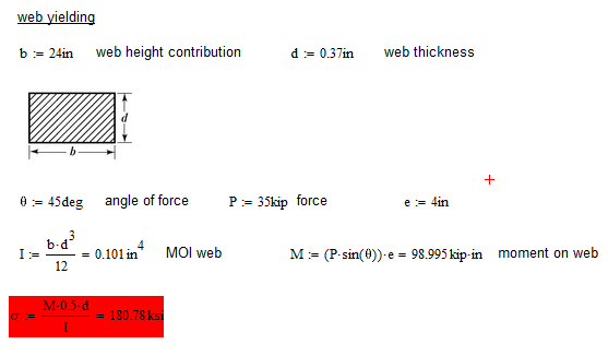
For the effect that you mentioned to occur, with the flange hinging about a point on the web, the cross-section can be checked for a calculated torsion force to see if it yields to form the plastic hinge? The problem would be determining the length of the beam web that participates in the strength. I very un-conservatively assumed 2 ft contributes and did a quick calculation and I think you are very right.

web_yielding_ikjahq.png


edit: retired13 there are pre-qualified welds for skewed tabs in the back of chapter 10 of the AISC manual. This tab should have a two-sided fillet weld, larger on the obtuse side. I don't have my code handy or I would give you a snippet.
 
MegaStructures,

Sorry for my ignorance, but beware your situation when using fillet weld, even it is pre-qualified by AISC. A discussion on AWS forum regarding to skewed joint is quoted below for information.

I am looking at AWS D1.1-2006 because it is the one I have in my computer. There are few differences between the 2006 and 2008 editions with respect to groove welds, fillet welds, and skewed joints in Clause 2. Groove welds are addressed in clause 2.3.1, fillet welds are addressed in clause 2.3.2, and skewed joints in clause 2.3.3. Separate clauses, each covering different weld types. There is no mention of “fillet welds” in the clause on skewed t-joints. They talk about prequalified skewed T-joints with a reference to Figure 3.11, but they don’t talk about fillet welds in skewed T-joint in clause 2.3.3.1.

They talk about how the engineer is to specify the weld in a skewed T-joint and how the fabricator is to specify the weld size in a skewed T-joint in clause 2.3.3.2. There is no mention of fillet welds in that clause.

Likewise in the clauses that follow in clause 2.3.3, there is no mention of fillet welds. There is no mention of fillet welds until you get to clause 2.3.4 where fillet welds in holes and slots are addressed.

The size of the weld in a skewed T-joint is defined, as is the length. If the welds were considered to be “fillet welds” there would be no need to redefine them in clause 2.3.3, they were already defined (for a fillet weld in clause 2.3.2.

Older editions of D1.1 used to talk about fillet welds in skewed T-joints, but that terminology has fallen out of favor for several years.

I have included an excerpt from D1.1-2006. Where is the term “fillet weld” used in clause 2.3.3 Skewed T-joints?

I hope this helps to claify some of the confusion.

Best regards - Al
 
Status
Not open for further replies.

Part and Inventory Search

Sponsor

Back
Top