Tek-Tips is the largest IT community on the Internet today!

Members share and learn making Tek-Tips Forums the best source of peer-reviewed technical information on the Internet!

  • Congratulations cowski on being selected by the Eng-Tips community for having the most helpful posts in the forums last week. Way to Go!

Eccentric Shear Connection 6

Status
Not open for further replies.

MegaStructures

Structural
Joined
Sep 26, 2019
Messages
376
Location
US
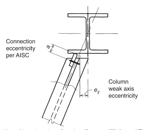
What additional failure modes to be checked for an eccentric skewed shear tab compared to a typical orthogonal shear tab. The shear connection supports high axial load as well as vertical shear and connects to a column flange.

I believe the only differences should be as follows
1) global analysis offsets need to be considered which increase torsion in the supporting column
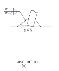
2) flange bending no longer follows the definition of J10.1 of the AISCM, instead the flange should be checked as a cantilever plate with infinite length per chapter 8 of Roarks. ASD safety factor of 1.67 still to be used for tensile yielding of the flange
3) The weld from shear tab to column will be analyzed slightly different to account for the difference in weld geometry

*Are there any other failure modes to consider in this connection not covered here?
*As a general question how does AISC control certain special cases like this where an approved code equation cannot be used? Is there a general blanket acceptance from the code that allows other analysis procedures per the EOR's discretion?

skewed_tab_lytxi8.png


Thanks
 
The other opinion:

Chris,
The AISC 13th edition of the Construction Manual addresses this condition(skewed shear tabs in the webs of beams)....several ways to approach the weld call out depending on the situation.

See AISC manual Table 10-13, pages 10-164(for 5/16" and 3/8" thick plate) and 10-165(1/2" plate)
Also see Figure 10-38 on page 10-151

note the skewed connections and that they use a fillet weld symbol on all but one, and they call it out as a BTC-P4 modified. Also note that some use the square edge of the skewed plate and others use a prepared edge on the skewed plate; where the plate meets the web.
 
A paper from AISC, which is very helpful for your situation. Link
 
Thank you for your contribution retired13, very good information. I'm not sure why there would be a discrepancy between AWS and AISC on allowing fillet welds for the joint, but I feel comfortable using AISC's method and I see no reason why it wouldn't work. Your link hit the nail on the head on page 5 showing the AISC approved weld.

skewed_plate_fillet_weld_wn0ybi.png
 
OK. Another AISC paper that contains the exact details as shown on yours (see Fig. 9). Link
 
OP: "I can put the shear tab on the opposite side, but the figure shown doesn't show correct ratios, there will still be a large eccentricity."

It would still be reduced... a good thing...

Dik
 
You’re absolutely right, Dik. There is improvement in that switch. Not a complete resolution however.
 
I would think the more complete resolution was what was proposed earlier using a stiffener to provide a sensible load path for axial load. Oh and recognise that there is some decent shear lag there, but likely fine.
 
I would imagine something like shown below subject to specific design would deal with the load path to engage the entire cross section.
Annotation_2020-02-16_133237_bwu7nj.png


The 35kip (135kN) force seems fairly small (to me at least), I was imagining large axial force = 1000kN or something.

The cleat with the bolt holes might also require some stiffening due to it being an eccentric connection as opposed to concentric connection for the axial loading component. Can't imagine with that small force it would be an issue though, but should form part of any robust procedure checking for eccentric axial compression connections.
 
MegaStructures said:
The geometry of the structure is such that the beams act as horizontal bracing for the MLFRS.

I feel that this entire discussion lacks something quite critical: an understanding of where this beam's axial load goes after it hits the column. Can you expand upon that? The overwhelming majority of the time, that axial load will either be:

1) Passed horizontally through the column to a another beam or:

2) Passed vertically through the column to a vertical bracing element.

Where the load ends up when it exits the column, and how it gets there, may significantly impact the choices that a thoughtful engineer would make with respect to the connection typology. It is possible that the engineer of record intended to for the beam axial force to truly die at the column as column shear, flexure, and torsion but I would consider that to be an extremely rare, and often unwise, decision on the part of the EOR.

MegaStructures said:
Adding stiffeners through a large project would be costly, so I feel like it should be proven that the stiffeners are needed.

I don't feel that it is the case that you should only add stiffeners if it can be proven that they are needed. Rather, I feel that you should only omit stiffeners if you can prove that they are not needed. Obviously, this thread only exists because you are struggling with the latter. Here, your imperative to please your client diverges from your imperative to safeguard the public. I get it, we've all been there. Frankly, we never really leave there.

In connection design, one must accept that much is, and always will be, unknown. Consequently, a measure of humility and conservatism is warranted. As an example, connection flexibility has not yet been mentioned in this discussion. A general principle of good steel connection design is to avoid force transfer via plate bending as much as possible. That, because plate bending implies behavior that is flexible and, therefore, less predictable. Yeah, we violate this principle on a pretty regular basis but, in my opinion, it's wise to stick to it in unconventional situations. See the sketch below for some flexibility related concerns that I have as well as some additional checks you might consider.

Agent666 said:
I would imagine something like shown below subject to specific design would deal with the load path to engage the entire cross section.

Love it. This is just the kind of direct and stiff load path of which I feel Blodgett would approve. That said, I do feel that we could improve upon it from a fabrication perspective without sacrificing intent.

As an aside, on a separate steel connection thread, skeltron once told me that it was a fire proofing no-no to create closed spaces like this. I'm not yet convinced of that, however, as skeletron did not elaborate upon this aspect of things in the other thread and, frankly, the objection doesn't really fit with my conception of how fire resistance is achieved in such situations. But, then, I'm hardly a fire proofing expert.

c01_cganwl.jpg


c02_px7kir.jpg
 
@KootK: The example you are referring to had a plate spanning between flanges and (I think?) stiffeners, creating a closed box. The design suggestion that you and @Agent666 also create closed boxes. I'm not a fire proofing expert. I have specified boxed out connections in the past only to have them flagged in review. They were flagged because the sequence to ensure fire-proofing in the closed space would take an out-of-sequence step in the fabrication assembly.
 
Thanks for your response skeletron.

skeletron said:
They were flagged because the sequence to ensure fire-proofing in the closed space would take an out-of-sequence step in the fabrication assembly.

That's the part that baffles me. My understanding is that the point of the fireproofing is to limit the heat input to the steel cross section. As such, there'd be no point fireproofing inside a steel enclosure because, by the time that heat got to that location, it would have already gotten everywhere within the steel section via conduction. It's not as though we typically fireproof the insides of HSS etc.

Certainly, I could see enclosed spaces potentially causing access problems etc.
 
Client specification in oil&gas plant was my situation. They didn't want this happening repeatedly at a number of bracing or beam-column connections. End verdict was a blanket solution to prevent any closed-box areas without fire-proofing.
 
sketron said:
End verdict was a blanket solution to prevent any closed-box areas without fire-proofing.

Sure, but do you at all understand the requirement to fireproof inside the closed box areas?
 
If the closed box areas are reasonably large (ie. 14" x 14" x 7" perhaps as a low-bound) and reasonably frequent or in essential locations (beam-to-column, or bracing) then I can understand the preemptive requirement to ensure fire-proofing on all surfaces. I believe that the comparison of an HSS column in a building versus a WideFlange column in an industrial environment differ in their situational risk.
 
So are you saying that, for spaces of a certain size, we're anticipating combustion inside those spaces? I'm still not hearing a rational explanation of the fire proofing strategy.
 
You would have corner clips on your stiffeners at the top and bottom of the boxed connection. So, yes, there would be a chance of combustion inside an otherwise closed-box connection which would be not continuously fire-proofed.
 
Gotcha. Maybe, by the same token, heated air can get inside if the thing's not airtight.
 
Status
Not open for further replies.

Part and Inventory Search

Sponsor

Back
Top