Continue to Site

Eng-Tips is the largest engineering community on the Internet

Intelligent Work Forums for Engineering Professionals

  • Congratulations cowski on being selected by the Eng-Tips community for having the most helpful posts in the forums last week. Way to Go!

Datum target cylinders? 5

Status
Not open for further replies.

semiond

Mechanical
Jan 9, 2011
176
Hello all,
Fig. 4-49 in ASME Y-14.5-2009 displays the use of datum target spheres.
I wanted to know if it is also acceptable to use datum target cylinders. I haven't seen an example in the standard and i'm not sure whether it is allowed or not.
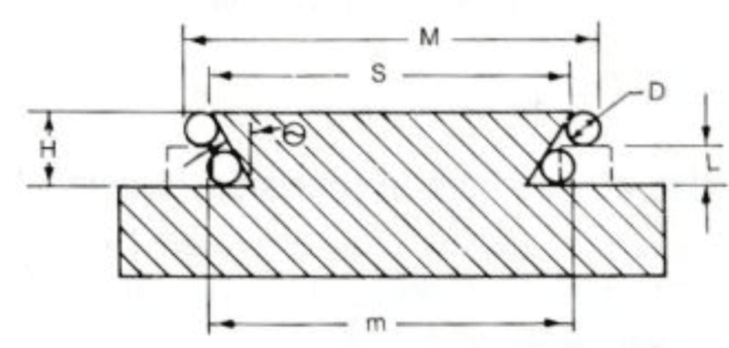
One case where this could be useful is parts with dovetail geometry (see picture); both for controling the dovetail taper surfaces themselves (profile of a surface referencing datum target cylinders with basic dimension distances) and for constraining degrees of freedom and establishing the DRF for the entire part.
20180604_062952_eq1jgs.png
 
Replies continue below

Recommended for you

semiond,
The idea of SIM REQT added to both profile callouts was to control both sides of the dovetail relative to each other in terms of orientation AND location, meaning that the size of the dovetail would also be controlled. That is why the directly toleranced dimension over the cylinders does not look good to me.

Is there any reason why you cannot rely on profiles to control width of the dovetail?
 
If i do that, would i need to replace the X dimension with a basic dimension connecting two opposing points on the slanted faces at some basically dimensioned location on the taper?
 
Yes. Or you could for example apply basic dimension between points B and D at the bottom of the dovetail.
 
pmarc said:
I am just not sure I like the directly toleranced dimension X over the cylinders...

pmarc said:
The idea of SIM REQT added to both profile callouts was to control both sides of the dovetail relative to each other in terms of orientation AND location, meaning that the size of the dovetail would also be controlled. That is why the directly toleranced dimension over the cylinders does not look good to me.

I would remove the reference to datum A (formed by datum targets) no matter what - someone please correct me if I'm wrong as there has been quite a bit of debate over its definition recently - but isn't this an example of another self-referencing datum? Datum A defined by the datum targets could be used to define another feature on the part but not the dovetail itself I would think. I know I'm probably opening a can of worms just mentioning it but it seems to me that the 2x examples semiond provided are flirting with being self-referencing if not already there.

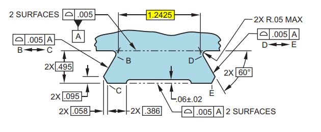
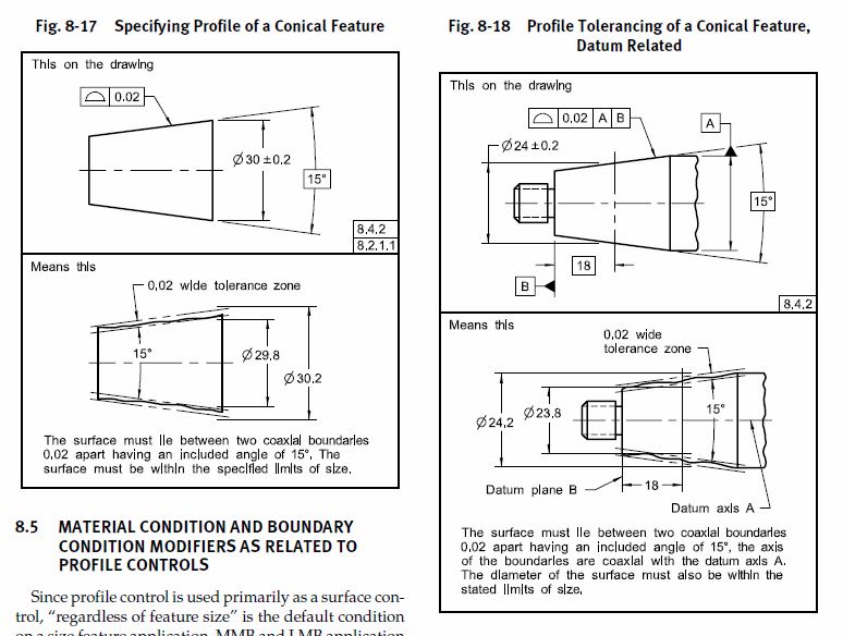
It seems to me that, like many things in GDnT, there is many ways to skin this cat. A few options come to mind like specifying an "over gauge pins/balls" toleranced dimension in conjunction with a profile callout - with or without datum targets (as long as they're not self referencing). Or dispense with the gauge pins/balls and directly dimension between each side of the dovetail at a defined point along the taper (think something like Figures 8-17/8-18 or 8-27 from Y14.5-2009 except applied to a dovetail). Or each part of the dovetail could be constructed separately utilizing angle tolerances.

Does anyone have an example of a "best practice" or a tried and true application showing an example of how to properly dimension geometry like this?

Of course pmarc's suggestion would work if as you say the size tolerance (over pins/balls - and any associated taper between each side of the dovetail) can be as tight as the form tolerance and vice-versa.
 
chez311 said:
Does anyone have an example of a "best practice" or a tried and true application showing an example of how to properly dimension geometry like this?

One of the possibilities:

"For every expert there is an equal and opposite expert"
Arthur C. Clarke Profiles of the future

 
 https://files.engineering.com/getfile.aspx?folder=ad26741a-9f34-4a32-b362-65da1a3a01e2&file=Dovetail_Dimensioning_Guide.pdf
CH: Please give me the ISBN number of the Whitmire book you got the dovetail PDF from.

Certified Sr. GD&T Professional
 
CH - thanks, thats actually very similar to one of the options I was envisioning although of course much more refined than what I probably would have come up with.

I'm sure I'll get conflicting answers here but in your opinion is there any reason the below basic width dimension couldn't be replaced with a directly toleranced dimension per my previous post?

dovetail_sstpou.jpg
 
chez311,
I agree that there are different (better or worse) ways to tackle the problem. CH just showed one more that does not use gage cylinders at all.

From my experience, methods that utilize gage balls/cylinders are still used because they are quite inspection-friendly when it comes to establishing datum plane(s) for measurement. The problem is that often the datum(s) is/are not derived from features that play the most important role in assembly (a.k.a. functional datum features), so in extreme cases this may lead to acceptance of parts that will not function properly in reality.

If the intent is to have looser tolerance on width of the dovetail than on its form, this can also be accomplished with profile tolerances only, that is with no directly toleranced dimensions. In CH's example the single segment profiles between points B<->C and D<->E would have to be changed to two composite callouts. The upper segments would show bigger tolerance values relative to A and the lower segments would show smaller tolerance values also relative to A. By definition of composite profile the mutual location of two dovetail sides (width of the dovetail) would then be controlled by the upper segments and form and orientation of the sides to the datum would be controlled by the lower segments.

In semiond's example it would be more difficult as he does not have any primary datum to use.
 
@chez311
"conflicting" doesn't even start to describe it.
There is no universal agreement about dimensioning taper / cone using Profile.
I guess in this case, as essentially all of the features controlled by profile anyway, using "true" dimensions to describe everything looks like a safe bet.

"For every expert there is an equal and opposite expert"
Arthur C. Clarke Profiles of the future

 
CH,
Do you have a similar exercise for slots as you show for dovetails? I just got an issue today and I am searching for proper dimensiong and tolerancing them.
 
pmarc said:
If the intent is to have looser tolerance on width of the dovetail than on its form, this can also be accomplished with profile tolerances only, that is with no directly toleranced dimensions. In CH's example the single segment profiles between points B<->C and D<->E would have to be changed to two composite callouts. The upper segments would show bigger tolerance values relative to A and the lower segments would show smaller tolerance values also relative to A.

pmarc - This is a very elegant solution, that did not occur to me. Thank you for explaining that!

CheckerHater said:
There is no universal agreement about dimensioning taper / cone using Profile.

CH - I don't mean to stir the pot, but do you take issue with the below examples from the standard? It seems to outline a pretty clear cut method for utilizing profile on a conical feature which I don't think would be much of a stretch to apply to flat tapers.

EDIT - I should have mentioned those figures are of course accompanied by section 8.4.2 - conicity

conical_profile_sgnr6f.jpg
 
Chez311,
Please search this forum for fig 8-18 and sure you will find different opinions regarding it. I know it is from the standard but not everyone is in agreement that this fig is the best thing that 2009 standard has.
 
Also in the next y14.5 revision (now draft) this 8-18 figure is going to be "adjusted"-replaced by a new one (with delta modifier) and, hopefully, all disagreement will be gone.
 
greenimi - I did a quick search and found a few threads discussing this topic in depth, I'll definitely be reviewing them at length but safe to say I did not mean to derail this thread into that discussion. It seems the topic is much less cut and dry than I initially thought it to be.

Consider my questions regarding profile controls of conicity/taper and 18-8 retracted!
 
Thank you for the input everyone, it's been fascinating to read.

In the example CH showed, which doesn't involve gage cylinders, would it be acceptable to simply show a reference 60 deg. angle between the two opposing angeled surfaces and attach a datum feature symbol next to it, similary to how it's done for the width dimension of a regular feature of size to say "center plane datum"?
 
If you get a copy of the 2009 standard, you'll be interested in the contents of chapter 4.
 
@chez311:
To close "conicity" discussion, if you have access to this book ( it has entire chapter on dimensioning cones - definitely not "cut and dry".

@Kedu:
This is the best I could find:

"For every expert there is an equal and opposite expert"
Arthur C. Clarke Profiles of the future
 
Status
Not open for further replies.

Part and Inventory Search

Sponsor