Continue to Site

Eng-Tips is the largest engineering community on the Internet

Intelligent Work Forums for Engineering Professionals

  • Congratulations cowski on being selected by the Eng-Tips community for having the most helpful posts in the forums last week. Way to Go!

Datum Shift 4

Status
Not open for further replies.

pyromech

Mechanical
Jul 30, 2008
39
Folks

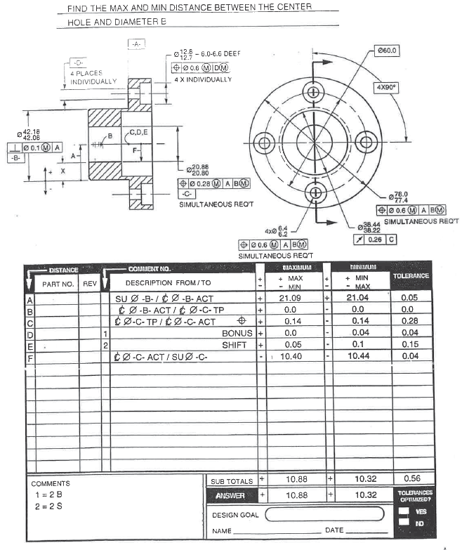
I am confused about datum shift. In the counterbore stack, we see them bilateral in Line D & P. But in the other stack, they are bilateral unequal, Line E. Is 0.1/.005 come from the perpendicularity control. Also, Where Line F, G, Line J, K come from. The position tol has been accounted already in Line B&N

thanks

Ex54_fq7eue.png
 
Replies continue below

Recommended for you

In that format of doing stacks, the shift tolerance is not really equal bilateral or unequal bilateral. Instead, it has to do with whether your stack goes only to the axis of the datum feature, or to the wall of the datum feature. For the graphic embedded in your post (the stack that has rows A through F), the stack begins at the wall of the datum feature, so the shift values are different because the actual diameter of the feature (well, the radius) plays a role in the shift.

But for the longer stack that was attached to your post, the datum D is only used in the stack for its axis; the stack path never touches the wall of that through-hole. Thus the size variation of the datum feature doesn't play a role in the shift.

If you have the textbook where those exercises are taken from, look back to a page in the bonus & shift chapter which shows a "bonus/shift chart." (In my version, it's on page 12-3.) The right-hand side of that chart explains how to enter the shift tolerance in the stack. Your shorter exercise would be considered stack condition 2 and your longer exercise would be considered stack condition 1.


John-Paul Belanger
Certified Sr. GD&T Professional
Geometric Learning Systems
 
Anyone know why "SIMULTANEOUS REQ'T" is used in that example when that's the default?

I know I am missing something simple, but what do SU and ACT stand for?

The embedded graphic phrases the question oddly - "What is the max and min wall thickness?" would have been more clear.

The main thing is that the wall thickness problem is not symmetric, so the tolerance is not symmetric.
The counterbores are equally disposed from their true position at their maximum and minimum so the tolerances are equally disposed.

FG,JK come from the individual position tolerances on the c'bores. There are two holes and two counterbores, each with a bonus and shift, so that should be eight lines on the analysis, which is how many lines are used for them on the table.
 
SU and ACT stand for surface and actual, respectively. These are among many of the unique abbreviations used in that textbook by Alex Krulikowski (a table of abbreviations is given in that book).

You can tell this drawing uses the 1982 standard, and even back then paragraph 5.3.6.2 recognized simultaneous requirements, so the note wasn't really needed. However, I think for a while General Motors (from whence Alex came) had an internal rule about separate requirements being the default -- I don't exactly recall. So apparently he felt it's safer to just add the simultaneous req't note.

John-Paul Belanger
Certified Sr. GD&T Professional
Geometric Learning Systems
 
3DDave said:
There are two holes and two counterbores, each with a bonus and shift,
Completely forgot about the holes. But why is the bonus treated differently from the counterbores. I would given them 0.05" as well. So the shift tolerance on the counterbores is half Pos Tol plus Dia Bonus tol (0.6/2 +0.1) instead of half of bonus Tol since we're using radiuses. And in the image, the shift Tol is Perp Tol plus half bonus Tol (0.1+ 0.05). How would i determine where the shift goes, tores LMC or MMC?

thanks Belanger.
 
J-P and/or everyone,

I am using VC and RC boundaries to calculate the stacks.
For the embedded picture I could get the same results as the ones shown in the book (max and min calculations match), but for the attached one (stack shown in the attachment and the more complex one) I am not ABLE to get the same results. I have no idea what I am missing.

Maybe the stacks CANNOT be done using VC and RC for this particular circumstance? Could you help?

Since the C'bore are references to D (at MMC/MMB) and the holes are to A primary and B secondary (at MMC/ MMB), could that be a reason on why Vc and RC does not work or most likeliy I have done something wrong.

 
aniiben -- yes it's possible to do those stacks with the VC/RC method. It just happens that the format given by the OP is the one favored by that textbook. Some people find it confusing because the shift tolerance is determined by something that might be several rows above or below the shift line in the spreadsheet. On the other hand, the VC method requires you to also do a bunch of side calculations to enter the data properly.

I'll have to take some time tomorrow to try that longer stack using your method...


John-Paul Belanger
Certified Sr. GD&T Professional
Geometric Learning Systems
 
JP - Thanks. The GM connection makes sense. In companies large and small there is no problem related to following rules that cannot be managed by creating more rules.
 
Code:
I am using VC and RC boundaries to calculate the stacks.

Do you mind posting the stack so others can chime in?
 
aniiben,

The VC/RC approach will work only if these extreme boundaries exist within one frame of reference and no other datum systems are involved in calculations. It is true in case of embedded stack-up because everything is calculated within datum system created by primary datum feture A at RMB and secondary datum feature B at MMB, but is not true for the attached stackup. In this stack-up different frames of reference are involved [D(M) and A|B(M)] thus if you want to use the VC/RC approach you should also add to the stack-up tolerances that come from geometric characteristics that control relationship between datum feature D relative to A|B(M).

It is just a guess, but are your calculated values 46.5 for MIN distance and 47.9 for MAX distance? If that is true it is because you have not taken into account the fact that each individual datum feature D has its own position tolerance relative to A|B(M) that gives extra 0.4 of radial displacement for each of the two holes D when produced at LMC, AND most likely you have not taken into account two radial datum feature D shifts of 0.4 that will be possible in case of positional tolerances for c'bores, because each c'bore is positioned indiviudally to its corresponding datum hole D.

This in total gives extra 1.6 of tolerance which needs to be subtracted from 46.5 in case of MIN distance calculation, and added to 47.9 in case of MAX distance calculation.
 
The VC/RC method definitely works for the shorter stack that was embedded in the OP. I have attached a simple Excel file that shows how that might work. (To make it work with this type of spreadsheet, the numbers entered are the LMC value along with a plus/minus tolerance. Don't let this confuse you -- if you calculate the VC and RC for a given diameter, it so happens that the midpoint of the VC and RC is the LMC. The plus minus numbers then yield the VC or RC.)

However, it doesn't work with the longer stack. The reason is that the longer stack uses only the axis of datum D in the calculation -- not the actual wall of that datum feature. If you do a simple sketch of any VC or RC, you'll notice that it's all about finding where the wall of the feature lies. But when we are stacking only axis to axis (such as from one datum D to the other datum D), the VC and RC are less relevant.
I just read pmarc's post and I think this is the same idea he was saying.

John-Paul Belanger
Certified Sr. GD&T Professional
Geometric Learning Systems
 
 http://files.engineering.com/getfile.aspx?folder=db5ae1e1-515d-4afd-91f8-429b8fd108d6&file=ShorterStackVCRC.xls
I was thinking about something slightly different, J-P.

If, for example, in the longer (attached) stack both c'bores were positioned to A|B(M) (i.e. gaged simultaneously), it would be okay to subtract two times the radius of c'bore RC from basic 60 to get minimum possible distance between the edges of the c'bores. And consenquently, it would be okay to subtract two times the radius of c'bore VC from basic 60 to get maximum possible distance between the edges of the c'bores.

So we would be able to apply VC/RC approach even though we never used actual wall of datum feature (B in this case). We would be able to apply VC/RC approach because these extreme boundaries were positioned relative to the very same datum reference frame.
 
pmarc said:
It is just a guess, but are your calculated values 46.5 for MIN distance and 47.9 for MAX distance
Yes. That is correct. And as a matter of fact I never used VC and RC of the holes (not the C'bores) to get the numbers you wrote above (X max.: 47.9 and x min.: 46.5)

I am trying to understand what I am missing....did not fully get it yet...... and to be honest I am also using

Subject: Query regarding Wall thickness calculations

and

Subject: Question on Book-Minimum Wall Thickness Calculations Using Tolerance Stack-Up Analysis

Are those good references for what we are talking about here or just create more confusion...?

Thank you pmarc for your input
 
There are two main schools of thought when it comes to stacks, and the leading proponents have been Mr. Krulikoski and Mr. Meadows. The Krulikowski method is the one shown in the OP's question, and it is based on the max and min for each dimension entered in the stack. The Meadows method looks at the nominal and plus/minus for entering the data in a stack. Both have advantages, but I've found that when it comes to bonus and shift that the Krulikowski method seems easier. But my early training in this stuff could be a factor in that. (Pyromech likes the Krulikowski method and Aniiben likes the Meadows method.)

The Excel file that I posted earlier is an attempt to bridge those two methods: It sort of looks like Krulikowski's spreadsheet, but it was tweaked to allow the nominal (either positive or negative) and then the plus/minus numbers to be entered.

This worked fine for the shorter (embedded)stack in the OP. But pmarc -- my concern on the attachment stack really was about the axis-only idea in the shift, because this tweaked version of the spreadsheet doesn't have an easy way to capture that. Take a look at the file attached to this post, and you'll see what I did to make the answer come out correct. I used VC/RC for the two counterbores, but to relate each datum D back to datum B, I just lumped all of the error into the jump of 60 across the bolt circle. Yes I got the correct answer, but it doesn't use the VC/RC of the datum as we would normally try to do with that method.

John-Paul Belanger
Certified Sr. GD&T Professional
Geometric Learning Systems
 
 http://files.engineering.com/getfile.aspx?folder=231b57b2-75d3-488c-896e-bde39c662d8c&file=LongerStackVCRC.xls
A common fact between datum shift calculations shown on both books is that the datum shift is "doubled" (.400 in " J. Meadows" case and 0.8 (0.6+0.2) in "pmarc's case/OP related case"---so to speak).
No doubt that both are correct. How to wrap my head around these calculations that is another story.

 
For the case of the wall thickness (image embedded in original post), I get the same answers: 10.32 and 10.88.

For the case of the distance between counterbores (PDF attached in original post), here are my attempted calculations:

[pre]
60 / 2 % center to through-hole true position
+ (6.2 - 0.6) / 2 % center to outer edge of through-hole position tolerance boundary
- 6.4 % center to inner edge of through-hole
+ 6.2 / 2 % center to datum axis D
+ (12.7 - 0.6) / 2 % center to outer edge of counterbore position tolerance boundary
- 12.8 % center to inner edge of counterbore
* 2 % inner edge of counterbore to inner edge of counterbore
= 45.5 % X_min

60 / 2 % center to through-hole true position
- (6.2 - 0.6) / 2 % center to inner edge of through-hole position tolerance boundary
+ 6.4 % center to outer edge of through-hole
- 6.2 / 2 % center to datum axis D
- (12.7 - 0.6) / 2 % center to inner edge of counterbore position tolerance boundary
+ 0 % center to inner edge of counterbore
* 2 % inner edge of counterbore to inner edge of counterbore
= 48.9 % X_max
[/pre]
I didn't try terribly hard to decipher the original calculations, but I believe lines D and P are the cause of the disagreement. It's as if they used a MMB of diameter 5.6 instead of diameter 6.2 for datum features D. I'm not sure why that would have been done, considering the counterbore position tolerance references datum feature D as primary. Perhaps someone can offer some insight.

Note that the above assumes perfect form and orientation for all features. If the effects of orientation errors are considered, the answers change drastically.


pylfrm
 
pylfrm,

I agree with you. Since datum feature D is referenced primary at MMB in the position callout for c'bores, radial amount of datum feature D shift should not be 0.4 [(6.4-5.6)/2], but 0.1 [(6.4-6.2)/2] instead.

But this (no reference to A primary in the position callouts for c'bores), as you noted, adds another complexity to the problem. For both MIN and MAX calculations, tolerances coming from each individual hole D-c'bore pair should not be considered in the direction parallel to datum plane A, because each individual datum axis D may be rotated within position tolerance zone applied to datum feature D. This means that position tolerance zones for c'bores, which are perfectly centered at corresponding datum axes D, don't have to be parallel to each other in the end. If they don't have to be parallel to each other, the only way to really find MIN and MAX distance in question is to include depth of the c'bores and thickness of the shoulder in the calculations.
 
I am still struggling with the “longer” stackup…..(find the max. and min. distance between the counterbores holes (x) so I have a quick question for pmarc and/or J-P B and/or pylfrm:
Would the stackup change if “4 x individually” note would not be there (delete this note from the counterbores size requirements)?

Will simultaneous requirement be now (after “4 x individually” note is gone) implied for the counterbores or it’s implied anyway?
 
And I have a question of my own: how the stackup will change (if it does) IF datum feature D is called RFS? Position of c’bores to be altered to pos: Ø0.6 (MMC) relative to D (Datum feature D = RFS)
Thank you


pmarc,

Good point about the datum axis orientation issue. I should have included perfect datum axis orientation in my list of assumptions.


aniiben said:
Would the stackup change if “4 x individually” note would not be there (delete this note from the counterbores size requirements)?

Will simultaneous requirement be now (after “4 x individually” note is gone) implied for the counterbores or it’s implied anyway?

In the original drawing, the four counterbore position tolerances are not part of a simultaneous requirement because they do not have common datum feature references (despite using a single datum identifying letter). Removing "4 X INDIVIDUALLY" AND "4 PLACES INDIVIDUALLY" will make datum feature D into a single pattern of four holes, and the four counterbore position tolerances will apply as a single simultaneous requirement. The answers would then be 46.5 and 47.9, again ignoring the (now relatively small) effects of orientation errors.


greenimi said:
how the stackup will change (if it does) IF datum feature D is called RFS?

If datum features D are referenced RMB, the datum axis in each hole will no longer be able to shift in whatever direction minimizes or maximizes the value of X.

pylfrm
 
Status
Not open for further replies.

Part and Inventory Search

Sponsor