Continue to Site

Eng-Tips is the largest engineering community on the Internet

Intelligent Work Forums for Engineering Professionals

  • Congratulations cowski on being selected by the Eng-Tips community for having the most helpful posts in the forums last week. Way to Go!

Datum Shift 4

Status
Not open for further replies.

pyromech

Mechanical
Jul 30, 2008
39
Folks

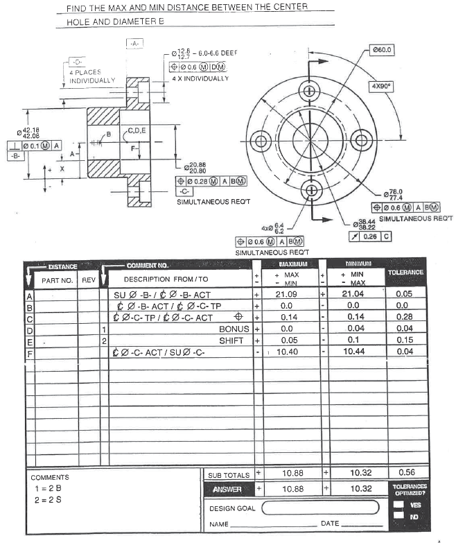
I am confused about datum shift. In the counterbore stack, we see them bilateral in Line D & P. But in the other stack, they are bilateral unequal, Line E. Is 0.1/.005 come from the perpendicularity control. Also, Where Line F, G, Line J, K come from. The position tol has been accounted already in Line B&N

thanks

Ex54_fq7eue.png
 
Replies continue below

Recommended for you

pylfrm said:
The answers would then be 46.5 and 47.9, again ignoring the (now relatively small) effects of orientation errors.

pylfrm,
Are you sure that if only "4 X INDIVIDUALLY" AND "4 PLACES INDIVIDUALLY" are removed from the problem statement/ drawing then the "new values" are the ones you indicated in your above quote?
I am not saying that you are incorrect, it's just seems strange to me.

As pmarc indicated earlier, the values 46.5 and 47.9 (for minimum and maximum X distance, respectivelly) are when---see pmarc's quote below

.... again....I know for sure I am missing something.....not sure what.

pmarc said:
[/It is just a guess, but are your calculated values 46.5 for MIN distance and 47.9 for MAX distance? If that is true it is because you have not taken into account the fact that each individual datum feature D has its own position tolerance relative to A|B(M) that gives extra 0.4 of radial displacement for each of the two holes D when produced at LMC, AND most likely you have not taken into account two radial datum feature D shifts of 0.4 that will be possible in case of positional tolerances for c'bores, because each c'bore is positioned indiviudally to its corresponding datum hole D.quote]
 
pylfrm said:
If datum features D are referenced RMB, the datum axis in each hole will no longer be able to shift in whatever direction minimizes or maximizes the value of X.

And to follow up on my own question, what would be the new values (X min and X max) if D is RFS?
 
I know…the end users (myself and maybe others) have a lot of questions for the experts.

The closest (to the “correct” book values) Xmin and X max values that I can came up with are:
Xmin: 45.7 and
X max. : 48.7.
I’m missing 0.8 from each value to get to the book values.
Not sure where the additional 0.8 should be driven from, but here are “my” calculations:

X min: 59.2 - 13.5 = 45.7
59.2 = 60 - 0.8 (max bonus on D)—max bolt circle diameter located at 60 basic )
13.5 = resultant condition for the c’bores

Xmax: 60.8 - 12.1 =48.7
60.8 = 60 + 0.8 -minimum bolt circle diameter located at 60 basic
12.1 = virtual boundary for the c’bore

My values (Xmin: 45.7 and X max. : 48.7) are closer to pylfrm’s values ( Xmin: 45.5, Xmax: 48.9), but nevertheless still a difference.
0.2 would be the differences between pylfrm’s values and mine.
If one of the experts can explain where this discrepancy came from I will greatly appreciate that. I am learning tolerance stackup. Not sure I will ever understand it completely.

 
Perhaps it is just my impression, but I have a feeling that a clarification is needed here. This will be about the second stack (the one attached to the OP).

First, the key input for the discussion is pylfrm's post from 25 May. Up to that point I had been too focused on trying to explain to aniiben the difficulties/limitations of VC/RC approach in stack-up calculations that I simply missed one very important thing - the counterbores in question are positioned individually to D(M), not to A|D(M), which in consequence means that the calculations shown in the workbook are... how to put it... wrong. One thing is that the datum feature shift values in rows D and P shall not be 0.4, but 0.1 instead. And additionally, even with the values in rows D and P corrected, we would have to make a bunch of assumptions about perfect orientation of considered features relative to each other, which is not what we are told to do. To be able to calculate Xmin and Xmax correctly (without a need of making any assumptions), we would have to know the flange thickness and would have go into trygonometry - this is what I tried to explain in my post from 26 May.

Also, assumptions would not have to be made, in my opinion, if the positional callout for counterbores was referencing |A|D(M)|. In that case correct answers would be Xmin = 45.5 and Xmax = 48.9, as given by pylfrm.

------

Then some follow up questions were thrown in, which essentially have been also answered by pylfrm:

1. What would happen if '4X INDIVIDUALLY' and '4 PLACES INDIVIDUALLY' notes were removed (aniiben)?
Then the position callout for counterbores would be treated as simultaneous requirement meaning that no datum feature D shift would be included in the calculations (line D and P from the original stack would be 0). Additionally, since the stack would not need to include position tolerance of thru holes D relative to datum axis B, unlike in the original stack, lines F, G, H, J, K, L would go away. That would result in Xmin = 46.6 and Xmax = 47.9.

2. How will the stackup will change if datum feature D is called RMB (greenimi)?
If the question is about modification of the original stack, not modification of aniiben's modification, datum feature shift values in lines D and P in the original stack shall be 0. This gives Xmin = 47.4 and Xmax = 48.7. Again, these values are true if assumptions about perfect orientation of all considered features relative to each other are made.
If the question is about modification of aniiben's modification, the answer is Xmin = 46.6 and Xmax = 47.9. So this actually means that it does not really matter what material boundary condition (MMB, LMB or RMB) the datum pattern D is referenced at in the positional callout for counterbores - Xmax and Xmin values stay unchanged. It is because the stack is calculated between features that are gaged simultaneously in both cases.

3. And finally, aniiben's question about missing things in his/her calculations/thought process that result in Xmin = 45.7 and Xmax = 48.7.
The difference of 0.2 in both cases comparing to pylfrm's answer comes from the fact that you did not include two radial datum feature D shifts of 0.1 that are possible if both individual thru holes are made at LMC [0.1 = (6.4-6.2)/2].
 
Again I will assume perfect form and orientation for all features and axes, except as noted.


greenimi said:
Are you sure that if only "4 X INDIVIDUALLY" AND "4 PLACES INDIVIDUALLY" are removed from the problem statement/ drawing then the "new values" are the ones you indicated in your above quote?

I stand by my answers of X_min = 60 + 12.1 - 2 * 12.8 = 46.5 and X_max = 60 - 12.1 = 47.9. I don't know why pmarc has X_min = 46.6.


greenimi said:
And to follow up on my own question, what would be the new values (X min and X max) if D is RFS?

Here are my calculations:

[pre]
60 / 2 % center to through-hole true position
+ (6.2 - 0.6) / 2 % center to outer edge of through-hole position tolerance boundary
- 6.4 / 2 % center to datum axis D
+ (12.7 - 0.6) / 2 % center to outer edge of counterbore position tolerance boundary
- 12.8 % center to inner edge of counterbore
* 2 % inner edge of counterbore to inner edge of counterbore
= 45.7 % X_min

60 / 2 % center to through-hole true position
- (6.2 - 0.6) / 2 % center to inner edge of through-hole position tolerance boundary
+ 6.4 / 2 % center to datum axis D
- (12.7 - 0.6) / 2 % center to inner edge of counterbore position tolerance boundary
+ 0 % center to inner edge of counterbore
* 2 % inner edge of counterbore to inner edge of counterbore
= 48.7 % X_max
[/pre]
I don't know why pmarc has X_min = 47.4.

Note that the assumption of perfect form is important here. Non-cylindrical through-holes would allow the answers to remain arbitrarily close to 45.5 and 48.9.


aniiben said:
My values (Xmin: 45.7 and X max. : 48.7) are closer to pylfrm’s values ( Xmin: 45.5, Xmax: 48.9), but nevertheless still a difference.
0.2 would be the differences between pylfrm’s values and mine.

As pmarc said, it is because you did not include datum shift. Note that your answers match mine for greenimi's RMB scenario.


pmarc said:
Also, assumptions would not have to be made, in my opinion, if the positional callout for counterbores was referencing |A|D(M)|. In that case correct answers would be Xmin = 45.5 and Xmax = 48.9, as given by pylfrm.

I disagree here. Referencing A as primary changes the MMB of datum features D from diameter 6.2 to diameter 5.6, making the answers 44.9 and 49.5. This is actually the result shown in the PDF attached in the original post.


pylfrm
 
pylfrm,
This is what happens if someone (me in this case) does not double-check his reply and numbers before posting it. And this is how instead of clarifying things more mess can be done.

So I will just re-post my long comment with modifications in red. Hopefully this time with no error:

-----------

Perhaps it is just my impression, but I have a feeling that a clarification is needed here. This will be about the second stack (the one attached to the OP).

First, the key input for the discussion is pylfrm's post from 25 May. Up to that point I had been too focused on trying to explain to aniiben the difficulties/limitations of VC/RC approach in stack-up calculations that I simply missed one very important thing - the counterbores in question are positioned individually to D(M), not to A|D(M), which in consequence means that the calculations shown in the workbook are... how to put it... wrong. One thing is that the datum feature shift values in rows D and P shall not be 0.4, but 0.1 instead. And additionally, even with the values in rows D and P corrected, we would have to make a bunch of assumptions about perfect orientation of considered features relative to each other, which is not what we are told to do. To be able to calculate Xmin and Xmax correctly (without a need of making any assumptions), we would have to know the flange thickness and would have go into trygonometry - this is what I tried to explain in my post from 26 May.

Also, assumptions would not have to be made, in my opinion, if the positional callout for counterbores was referencing |A|D(M)|. In that case correct answers would be Xmin = 44.9 and Xmax = 49.5, as shown in the book.

------

Then some follow up questions were thrown in, which essentially have been also answered by pylfrm:

1. What would happen if '4X INDIVIDUALLY' and '4 PLACES INDIVIDUALLY' notes were removed (aniiben)?
Then the position callout for counterbores would be treated as simultaneous requirement meaning that no datum feature D shift would be included in the calculations (line D and P from the original stack would be 0). Additionally, since the stack would not need to include position tolerance of thru holes D relative to datum axis B, unlike in the original stack, lines F, G, H, J, K, L would go away. That would result in Xmin = 46.5 and Xmax = 47.9.

2. How will the stackup will change if datum feature D is called RMB (greenimi)?
If the question is about modification of the original stack, not modification of aniiben's modification, datum feature shift values in lines D and P in the original stack shall be 0. This gives Xmin = 45.7 and Xmax = 48.7. Again, these values are true if assumptions about perfect orientation of all considered features relative to each other are made.
If the question is about modification of aniiben's modification, the answer is Xmin = 46.5 and Xmax = 47.9. So this actually means that it does not really matter what material boundary condition (MMB, LMB or RMB) the datum pattern D is referenced at in the positional callout for counterbores - Xmax and Xmin values stay unchanged. It is because the stack is calculated between features that are gaged simultaneously in both cases.

3. And finally, aniiben's question about missing things in his/her calculations/thought process that result in Xmin = 45.7 and Xmax = 48.7.
The difference of 0.2 in both cases comparing to pylfrm's answer comes from the fact that you did not include two radial datum feature D shifts of 0.1 that are possible if both individual thru holes are made at LMC [0.1 = (6.4-6.2)/2].
 
All this for a pretty simple arrangement - It's too bad that VSA isn't more widely available.
 
3DDave,
I do not know to work with VSA, but do you think this software is capable to do this kind of calculations (min / max calculations for individual features on the same part)?
I read that VSA is good to work with individual assemblies (multiple solidmodels loaded) and no so much with individual parts (relationship within the features on the same part). If you have experience with VSA could you please offer some insights? I am trying to learn more.

Also, in my opinion, if this kind of simple arrangements ---(and I agree with you: there are simple in the complexity of the entire assembly, probably, as shown by the OP ---both examples) are not properly understood (and I do not claim I do it) then the VSA will be a good and expensive number generator. Sometimes they make (those softwares) worthless sheet of paper.

More or less as the CMM it is. If the values on the CMM report are not understood to a certain level, then are just that: numbers.


Using VSA was my sole occupation for 8 hours a day for around 9 months. It is quite good at making estimations of probable real-world results and it works just as well on single parts as for complex assemblies; it first generates individual part variations and then assembles them with assembly variations.

One of the outputs of VSA is the solution method, which is the actual program it runs to do the simulations, so it's not just numbers. Just look at the sequence of transforms to see how the final results are arrived at.

Cookbook calculations don't do so much for understanding. They are shortcuts developed to solve particular sorts of problems and often require simplifying assumptions, such a perfect orientation, to do what they do. They also don't handle the distribution of variations that production parts will experience, and therefore are useless for predicting production yields.

What does help understanding is to draw parts that have features with compliant but extreme variations and see what combinations make for worst cases and to look at controls that limit those variations. If a person understands the qualitative effects of allowable tolerances, then the rest can be worked out.
 
I know the stars are not the most important thing here, but I think that one person deserves waaay more credit than me for the input provided to the discussion.

A star for you, pylfrm. Great job!
 
3DDave,

I notice the following bullet point on the VSA product overview:

[URL unfurl="true" said:
https://www.plm.automation.siemens.com/en_us/products/tecnomatix/manufacturing-planning/dimensional-quality/variation-analysis.shtml[/URL]]CAD neutral flexibility leverages embedded product and manufacturing information (PMI)

Seems rather optimistic considering the slow progress with STEP AP242 and such, but perhaps I'm out of the loop. When you used VSA, were you able to import tolerancing with the CAD models, or did it have to be entered manually after importing geometry?

Also, any idea about the cost?


pmarc,

Thanks.


pylfrm
 
3DDave... While VSA might be great for the real-world use of these stacks, there's still a place for people to learn how to do them the old-school way. After all, even with calculators a good engineer should understand the concepts behind mathematics.

John-Paul Belanger
Certified Sr. GD&T Professional
Geometric Learning Systems
 
pylfrm, I used the version they integrated with Pro/E. So all the tolerances, dimensioning schemes, and feature controls were available to the VSA software. The complaint from the VSA developers was over PTC withholding the code to automatically relate the dimensions to the relevant surfaces, which meant a short cleanup step to pick each dimension and the surfaces it controlled. After that step the VSA data remained embedded in the model so it would not have to be repeated if used again or in a different assembly or if the values or tolerances were changed.

I expect it still costs a lot more than people like, because why not? It's only bought by those who can see some value in good control of their product variation and it seems like few have that desire**. The version I used was about $10k for the seat and a few grand for the annual maintenance, but that was directly from VSA Inc, long before Seimens bought it along with UG. PTC stuck with the less flexible Ti-Tol/Raytheon/whatever originating from ADCATS and that was that. Unlike most tolerance analysis software, because VSA generated intermediate C code, one could add in any conceivable module that was dimensionally dependent. Suppose one modeled combustion efficiency based on all the variations in chamber geometry, one could look at variations based on cylinder diameter or con-rod length. Likewise, if there was some other interdependency not readily represented by dims and FCFs, that could be accounted for as well.

JP - that's why I suggest skipping plug-and-chug in favor of creating images of variations. It's not possible to be sure the formula is right when the user has no idea what the part will be like. I have found it much better to learn how to derive the equations from the observable variations than to memorize special cases and their list of assumption.

** I have seen no evidence that anyone but big auto makers are interested. Perhaps no one else wants to walk as close to the manufacturing capability over so many parts in order to save manufacturing expense. Everyone I've been exposed to will slot holes and shoot for the nominal and hope for the best. They don't gather much data from manufacturing processes to use for yield predictions. The last place I worked the parts coming in didn't match the drawings, but it was OK as long as they fit in production. There had been e-mails about changes and the company never got around to updating their own docs, though the supplier updated their process. This is a company subject to FDA oversight. Their QA didn't notice because they only check on complaints and the first articles when they are included on the change notice.

Still it's not magic. Early on, one of the manufacturing engineers asked about analyzing a weldment for warping due to welding. I noted that the weldment was done without a fixture, the process called for a variable number of passes and the parts on the drawing didn't nominally fit but were sized to let the welder grind them to fit. But sure, a great candidate for a geometric tolerance analysis. Later on I got a manufacturing demand for a drawing change to allow more variation and to change all the welds from skip welds to continuous because "That's what the welders are doing." Can't have non-compliant parts if the drawing is changed on every production run to account for what manufacturing changed. If I say we really paid the piper, it would be an in-joke.
 
pmarc said:
The VC/RC approach will work only if these extreme boundaries exist within one frame of reference and no other datum systems are involved in calculations

pmarc,

Just a small caveat to your above statement:

See the same book, page 12-14 -example 5. One hole to A, C, D(MMC) and the other A, C and B.
VC and RC still works.

Ø 8.2-8.6 pos Ø.016 (MMC), A, C and D(MMC/ MMB)
VC: 8.04, RC: 9.16

Ø4.0-4.4 pos Ø 0.1 (MMC), A, C and B
VC: 3.9, RC: 4.9
16 basic dimension between the holes. (Calculate the max and min dustance between the edges of Ø 8.2-8.6 and the Ø 4.0-4.4)

I guess we can call it two different datum systems/ two different setups or coordinate systems.

VC and RC approach still works. Am I correct?
 
greenimi,

I did not check each and every line of the stack you referred to, but to answer your question, the VC/RC approach will work in this case because change of tertiary datum feature references [B vs. D(M)] have no influence on what happens in vertical direction - the direction of the stack.

In other words, what makes VC/RC approach usable in this very scenario is the fact that both holes are positionally controlled relative to the same primary and secondary datum features A and C, and that the diffence in tertiary datum features has no influence on calculated distance.

If, however, the stack objective was to calculate the distance between the edge of the big hole in the center and the edge of dia. 8.2-8.6 hole, then the VC/RC approach would not work (at least not that easily).
 
Pmarc,
Is it safe to assume that VC/RC approach works on a limited bases only?

Personally, I like VC/RC, but looks like I cannot use it “all the time”

Also, for the “Kurlikovaski method” ---see first embedded graphic (not the attached one) exercise 12.4 page 12-23 from the book --- am I correct in saying that the perpendicularity error on datum feature B was not included in the stack for the X minimum because the author intended to include the datum shift ?

The natural question (s) for the experts is when you include one (perpendicularity) versus the other (datum shift) as is obvious we cannot include both?

 
aniiben,

1. Yes, I think you could say that VC/RC approach (without any tricky workarounds) works on a limited basis only.

2. The perpendicularity error on datum feature B is not directly shown in the stack, but it is included in the datum feature B shift calculations (see bonus/datum shift chart in the book).

3. Yes, I would say you cannot include both in the stack.
 
Thank you very much pmarc. I also tend to rely "too much" on the VC/RC approach. Not sure, why, but sometimes seems easier and easy does not mean correct.......

Do you agree also with my assessments on the VC and RC thread?
We used, for the sake of comparation, your "min wall" thread calculations where the form error on the datum feature must be taken in consideration to get the correct min wall values.
I made a statement there that IF the datum feature is at RFS then the form error should be included separately versus IF the datum feature is at MMB or LMB than the form error is already included/ or does not need to be included.

 
Status
Not open for further replies.

Part and Inventory Search

Sponsor