So much for me being done on this topic.
![[3eyes]](/data/assets/smilies/3eyes.gif "[3eyes] [3eyes]")
Celt83 said:
Human:
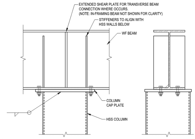
To be fair if you are going to model the top beam/column connection rigid then should probably also model the column base connection as rigid or a rotational spring. Also should probably have a rigid end offset between the beam and column to move the attachment to the beam base, the stiffeners will take care of the panel zone deformations.
True. I can't argue with that, you are correct. It was a quick model to show the point graphically. As far as base connections go I agree, I have also argued and modelled the behaviour of typical 'pinned' base connections which can readily be semi-rigid or rigidly connected to the footing. The footing however might behave in a pinned fashion for higher loads.
Celt83 said:
Your model deflections for the beam are actually quite similar so it would seem that in isolation designing the beam as pin-pin would be accurate.
I disagree. Just because minimal moment is being transferred (which is the corollary of minimal change in deflection) doesn't necessarily mean CURVATURE isn't being transferred. It is this curvature and the associated column deflections that are the issue I have been highlighting. It is also and issue I've seen in the field with my eyes, as has WesternJeb. It does not look impressive when the column has visible bend under simple dead load.
Celt83 said:
Not trying to discount the concerns with the column response and like the envelope approach.
I perform the envelope approach if I'm at all concerned. Regarding the column capacity, I've explored in depth previously on eng-tips, most of the time the what you lose in capacity in additional column moments you gain in capacity in reduced effective length.
milkshakelake said:
@human909 If it were a column under a cantilever beam for a balcony or some small load, would you still apply a rigorous analysis or let it go as pinned?
I'd normally design things as pinned and quickly move on. I have no problem with that approach without rigorous analysis only if you are "eyes wide open" regard the assumptions you are making and the potential consequences. Us structural engineers make simplifying assumptions all the time, sometimes knowingly sometimes unknowingly. But if we make such an assumption in the wrong circumstance then there can be issues. This is where engineering judgment comes into things.
This isn't new engineering. Engineers have known about the importance of pinned connections for centuries. It is just good judgement or good analysis that will reveal when it matters and when you can just forget about it.
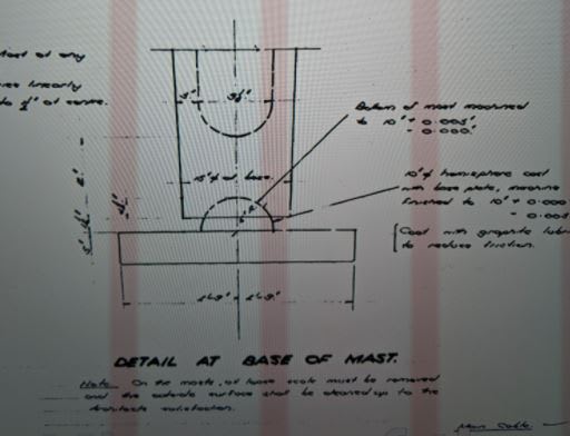
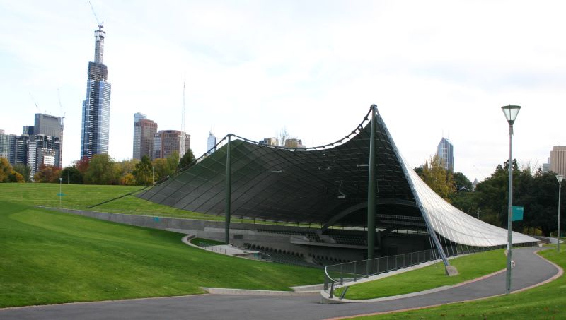
I've posted this previously but I'll post this again. This is the base connection from a 1956. The structure was prone to larger than average deflections and the column was designed to attract minimal moment. So they used a ball and socket joint.