sticksandtriangles
Structural
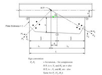
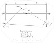
I am reviewing Design Guide 29, vertical bracing connections, and was struggling to understand the derivation of the internal gusset plate forces.
The images from the design guide are shown below.


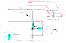
The force determination on section A-A, I understand and feel comfortable with. I get lost at the force determination on section B-B, Why is there a 1/2 applied on N'? Same thing for the V' determination. More questions to follow on the M' calculation, but let's start with the 1/2 question first.
The images from the design guide are shown below.


The force determination on section A-A, I understand and feel comfortable with. I get lost at the force determination on section B-B, Why is there a 1/2 applied on N'? Same thing for the V' determination. More questions to follow on the M' calculation, but let's start with the 1/2 question first.

