Eng-Tips is the largest forum for Engineering Professionals on the Internet.

Members share and learn making Eng-Tips Forums the best source of engineering information on the Internet!

  • Congratulations JStephen on being selected by the Eng-Tips community for having the most helpful posts in the forums last week. Way to Go!

Bug Zapper Ceramic Disc Capacitor Replacement

Bullrunner99

Industrial
Joined
Aug 8, 2023
Messages
3
Location
US
I am a novice with no electronic experience. This is a vintage SEARS BUGWACKER, MODEL 833.1432, INPUT 120V AC 60HZ 45 WATT, WITH A GRID MAX OF 5000V. The specs indicate 9 MA which I believe is milliamps. These insect zappers I believe were later known as Flowtron brand.

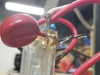
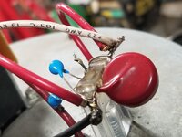
The two electrical grids are no longer electrified. Under the hood of the insect zapper are two ceramic capacitors. I assume them to be 5000 volts matching the product specs. I do not know the picofarad rating of the OEM capacitors? A repair handyman has determined that one capacitor failed.

I purchased Ceramic Disc Capacitors 100pf 0.1nf 101 10000V. The repair technician kept the one working OEM capacitor (5000V assumed) connected, and put two 10000V capacitors one the other side replacing the failed one. This seems imbalanced to me, since the two electrical grids on the zapper are still not electrified. The unit now has three capacitors, one OEM at 5000v and two 10000v.

Questions please:
  • Is it acceptable to replace the two OEM capacitors with ones having voltages above 5000, such as 7000 or 10,000 volts? Sourcing 5000v capacitors has been a challenge. Does this effectively increase the voltage capability of the elecrical grids?
  • How many picofarads is required on a replacement capacitor? Is a lower number better? Is 100pf acceptable, as purchased?
  • Do the two replacement capacitors need to be of the same voltage?
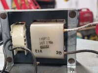
  • Might this be a Ballast or Transformer issue also?
  • Any sourcing help for these components would be appreciated.
I have replacement Starters available. The OEM Starter is FLOWTRON FS-25X 25W.

I do not have a manual for the exact model. Attached is one for a similar, but different model.

Thank you much.
 

Attachments

It is perfectly acceptable to replace a 5000V capacitor with a 10,000V capacitor.
One trick here is IF the value needed is 100pF, you could take two, 200pF capacitors of 2500V and connect them in series. This gives the equivalent of 100pF at 5000V. This works if the capacitors are identical in value/voltage.

The question is, what was the value of the original OEM capacitor.

The two "Ballast" transformers shown in the manual are likely for the florescent bulb light, and not part of the zapper. The FS-25X is a florescent bulb starter, same as you might find in a florescent desk lamp of 25 watts.

Item 12 in the manual appears to show the High-voltage step-up transformer. This appears to be a laminated silicon steel type (low frequency) which leads me to believe the design directly steps-up the incoming 60Hz AC rather than using a flyback-type transformer similar to what would be found in a CRT TV (a higher frequency in the kHz). What I'm getting at is 100pF may not be enough at a low frequency.

To get more pf connection to the grid, you can parallel the capacitors. Two 100pf 10,000V capacitors hooked in parallel give 200pF 10,000V worth of capacitance. It would help to get the capacitance of the OEM capacitor measured, then you would know what you needed.
 
Comcokid, thank you for your info. Attached are some pictures of the ceramic capacitors and what might be a transformer. I offer them incase this helps in any additional way.

I did not take these pictures. I am not sure they clearly show the wiring repairs and all capacitors. It looks to me that these are two separate wiring insulator terminals.

The larger diameter red capacitor(s) is OEM. My repair techinician has no way to test for picofarad value or capacitance. The smaller blue capacitors are the 100pf 0.1nf 101 10000V replacements.

Let me know if this info offers any additional help to your advice.
 

Attachments

  • 1751352051247.jpg
    1751352051247.jpg
    68.4 KB · Views: 3
  • 1751352051367.jpg
    1751352051367.jpg
    79.7 KB · Views: 3
  • 1751352051434.jpg
    1751352051434.jpg
    80.7 KB · Views: 3
I am no expert on bug zappers, and will make several guesses.

The size difference between the blue replacement and red OEM capacitors is a quick indication that you need more capacitance. The thickness of the disc is roughly related to working voltage. the diameter is roughly related to capacitance. I would guess the original is probably10kV or 15kV based on the pictures at Digikey (below).

A quick visit to a electronics parts house that will make small orders - DigiKey (www.digikey.com) shows possibilities.
I took a guess and searched for Ceramic Capacitors, Through hole, 10kV to 15kV and around 2200pF (2.2nF) to 4700pF (4.7nF). Search results show several "radial disc" capacitor. Examples - Kemet CGP1C472MNWDAAWL25 is 10kV 4700pF and $2.48 each Vishay 615R150GAD25 is 15kV and 2700pF$10.51 each. The Vishay part is even red, but the color doesn't matter and the pictures are representative - a close look reveals the value in the picture is a little different. You can always download a datasheet which has more pictures.

But again - this is all a guess. Good Luck!
 
One final suggestion for testing for the presence of high voltage. Neon bulbs are good for this. NE-2 neon bulbs can be found at DigiKey, and are are also found in panel mount power indicators and even in in those hardware store circuit checkers. You don't connect the bulb leads. For high voltage just bring the bulb up to the zapper electrodes and the E-field should excite the neon inside the bulb. tape it to the end of a long dry dowel rod. Also works for seeing if HV is present in those old CRT type TVs.
 

Part and Inventory Search

Sponsor

Back
Top