Tek-Tips is the largest IT community on the Internet today!

Members share and learn making Tek-Tips Forums the best source of peer-reviewed technical information on the Internet!

  • Congratulations TugboatEng on being selected by the Eng-Tips community for having the most helpful posts in the forums last week. Way to Go!

Beam Reinforcement Calculation 4

Nick6781

Structural
Joined
May 15, 2024
Messages
55
Location
CA
Let's say I need to use a web plate instead of a flange cover plate (I know...) to reinforce a beam. How do I calculate the required weld to ensure the section acts compositely? The shear flow equation gives the shear along a horizontal plane, but in this case, the faying surface is vertical. I can't quite wrap my head around it.


1751068113227.png
 

Attachments

  • 1751068099044.png
    1751068099044.png
    12.3 KB · Views: 5
This "diatribe" is relevant as it goes to the core of the original question.

The longitudinal shear flow between the plates and the I beam would be zero. All you need to do to have them act as a compositive section is to sister them together. So bolts or spot welds at the centroid would be sufficient.
 
This "diatribe" is relevant as it goes to the core of the original question.

The longitudinal shear flow between the plates and the I beam would be zero. All you need to do to have them act as a composite section is to sister them together. So bolts or spot welds at the centroid would be sufficient.
Shear flow between the I-beam and plates is not zero. Depending on the thickness of side plates, it may actually reduce the shear stress in the beam web for the height of side plates, but that is a questionable advantage since the shear stress in the remainder of the web remains the same as it was without side plates. So I see your point...side plates as shown in the original post are not useful. To sister the side plates is equally useless, so why not simply do nothing? Leave the I-beam alone.
 
Last edited:
Shear flow between the I-beam and plates is not zero.
I still disagree and have tried to make my point numerically, but have not had time for sketches or examples. Shear flow at that point may be non-zero, but shear flow between elements (in this case) is 0.

This has been shown numerically (see my previous post and sketch below)


Case I
1752242439255.png
This has been shown thru FEM - See detailed FEM approach above
This has been shown empirically via discussions about the two sections not being truly composite with examples such as comparison of Moment of Inertia and others.

There seems to be a basic disconnect on mechanics here and confusion between shear flow within the overall member at the top of the plate and shear flow being transferred to the plate. This topic is worth continued discussion as there seems to be some confusion on the topic and it gets brought up in here alot (although generally via a more"common member arrangement). Shear flow in the I shaped member at the top of the plate is not zero. But shear flow transferred across the joints to plates can be taken as zero as calculated above. BA - it seems like you are calculating shear flow as though the section is as below (full member joint at top of plat), but this is not the reality of the situation. Shear flow at the bottom of the WT "stays within" the W beam and is not transferred to the plates. (empirically, a section with a horizontal joint as shown below would behave differently than the web-plated beam above - and have more horizontal shear demand across the joint. It is my opinion that Case I would have no shear flow between elements and Case II would have shear flow across elements.

Case II
1752243954084.png
 

Attachments

  • 1752243944934.png
    1752243944934.png
    17.7 KB · Views: 1
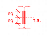
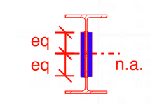
Just thinking allowed. Immediately below the top flange, there will be a shear flow in the web. Progressing down the web, the shear flow will increase. As you get to the top of the two side plates, the shear flow will suddenly be confronted with three load paths, into the side plates through the two welds and down the web. If you take the shear flow in the web at the bottom of the welds (two vertical sides), will the thickness be the two welds and the web (V.Q/[I.(2.t+w)]? One or two have posted something similar.

Edit: the weld thicknesses could be at the 45 degree plane (min weld section).

Edit: After reading a few more posts, I've noted that some are discussing the use of pins / bolts along the N/A, without welds. I understand this approach (zero axial strain, vertical shear only, etc). The comment made in this post was based on the original question, namely the use of welds.
 
Last edited:
I still disagree and have tried to make my point numerically, but have not had time for sketches or examples. Shear flow at that point may be non-zero, but shear flow between elements (in this case) is 0.
💙 THANK YOU! 💙

It has become quite circular and frustrating. But even then I've persisted because ultimately I have learnt a fair bit more about shear flow. You might have seen my grillage analysis that most people seemed to ignore. What was great about that was you could readily see shear flow, shear lag and it did improve my conception understanding.

There seems to be a basic disconnect on mechanics here and confusion between shear flow within the overall member at the top of the plate and shear flow being transferred to the plate.
Exactly.

It seems like some people have been blindly following text books and calculations for years without actually understand WHAT they are calculating.
 
Last edited:
It seems like some people have been blindly following text books and calculations for years without actually understand WHAT they are calculating.
Unless I am missing something, the numerical approach above does follow the "textbook" approach as far as I am aware; however it is not a case that is often covered in example problems for several reasons. It would have been a good"trick" question to throw in to a mechanics of materials textbook to push understanding of the concepts though..
 
On the other hand, Timoshenko and MacCullough seem to be quite convincing in their text "Elements of Strength of Materials". Below is their derivation of Formula for Horizontal Shearing Stress.

Perhaps human909 could point out the fallacy in their reasoning.


1752263715152.png
 
Last edited:
Unless I am missing something, the numerical approach above does follow the "textbook" approach as far as I am aware; however it is not a case that is often covered in example problems for several reasons. It would have been a good"trick" question to throw in to a mechanics of materials textbook to push understanding of the concepts though..
Agreed. A fantastic trick questions judging by the discussion in this thread.

Though and certainly multiple ways to approach it. As many here have argued you don't even need to calculate it. The centroids are at the same point so sistering them would provide the same out come. No connection to allow shear flow required.

On the other hand, Timoshenko and MacCullough seem to be quite convincing in their text "Elements of Strength of Materials". Below is their derivation of Formula for Horizontal Shearing Stress.

Perhaps human909 or RWW0002 could point out the fallacy in their reasoning.
Why would you expect that I or RWW0002 would find anything there controversial? I'm the one who has constantly been linking the mathematical definitions.

The fallacy is in your leap of application to expecting welds are required to transfer shear in a location where the strain of the adjacent un-joined sections is identical. Or in other words, the shear flow (per section area) is already EQUAL in the absence of welds, so adding welds want change anything.***
***Like always, in this discussion of course vertical load needs to be transferred. Sistering with centroid bolts would be my approach.
 
Last edited:
Regarding models:

Human909 in post #28. Don't think this one can settle it. Only 1 connection between doubler plate and beam. So horiz shear result is nett which everyone agrees is 0. Doesn't prove it isn't top and bottom welds summing to 0.

Human909 in post #62. Maybe could settle it but details not given. Looks like image is for beam without doublers?

Celt83 in post #81. Has details shown but might be showing display artefacts or analysis artefacts not true results. Results for horiz shear aren't symmetrical like they should be. But checked at 24 inches from midspan anyway. V=24. Q=1.531 inch^3 for half of 1 doubler. I=192.1 inch^4. Shear flow = 0.191 per inch = 2.296 per 12 inch weld spacing. Doesn't match analysis of 2.76. Wouldnt trust model yet given problem with results not symmetrical.

Main issue to me is no difference in strain at weld level so what stresses them? Look at cross section from other thread linked in post #14. Central plate with two channels welded at flage tips. I think shear flow between plate and channel there even though channel at centroid (Q=0) because shear lag at flange tips if just sistered. Also load at flexible flange tips can't drag channel web down effectively might contribute too. But don't have those issues with doubler plates. Will always get some minor issues like welds not fully rigid and plates not perfectly centred so some shear flow in real life but can't see full amount as though doubler are cut into top and bottom halves like calculated above.
 
Hey smoulder! :) Thanks for taking a thoughtful look at my posts, which hasn't always been evident in other replies.

Regarding your response. I agree entirely with your conclusions on my posts #28 doesn't fully expand to demonstrate a proof. And #62 doesn't contained the full depth of what was modelled. Nobody expressed any interest in seeing it until now so I haven't detailed it. My post was already too long! (to properly expand on it I would need another post twice as long.) I did model the doublers. But tweaking out the proof circles back to equal stress strain arguments which have largely been ignored so a model showing the same arguments doesn't add to the debate.

Will always get some minor issues like welds not fully rigid and plates not perfectly centred so some shear flow in real life but can't see full amount as though doubler are cut into top and bottom halves like calculated above.
Agreed. That this exists along with any shear lag if you are using staggered bolts for sistering. Etc... This was also evident in my computational model because unless you have a continuous connection then there will be some shear lag even if it is almost negligible (which it was).
 
Just brain-storming! A scenario ...
You have an I beam. You want to attach two side plates to the web.
Case 1) You put in two rows of pins evenly pitched (say 2in) 1/2in from the top and bottom edges of the side plates. The holes are slotted longitudinally. Outcome ... when the I beam is loaded, what contact loads will the pins see?
Case 2) Instead of slotted holes, you use bolts in interference fit holes. What will the bolt holes see as bearing load when the I beam is loaded?
 
I am in agreement that shear flow VQ/I at the tops of the side plates is 0.

I think that the horizontal shears manifesting in my model are a nuance of intermittent fastening being at points of non-0 rotation of the host section.

Assuming same material for the side plates then they would “take” a portion of the load equiv to Iside plate/Icomposite applied as a fully uniform load. Discretizing the uniform load into point loads at intermittent fastenings will produce slightly different rotations than a fully uniform load and with the welds being very stiff longitudinally and applied at points of non-0 rotation of the host W section I am thinking this leads to what are effectively compatibility couples to force the needed additional side plates rotation this would also explain why the couples reduce as you move toward the center of the span as the cross section rotations reduce to 0 at mid span.

With intermittent fastening that are either at the centroid, location of 0 rotation of the host W, or allow horizontal slip, independent rotation of the side plates, these couples would I believe not exist as the side plates rotations would be allowed to be different from the host W.
 
Glad to see you go back and look at your model. For what it is worth here is my model with discrete welds every 20mm. along with bolts every 20mm in the centre.
n)

1752346221784.png
It does show shear in the weld. But this is due to shear lag and their magnitudes 0.15kN are over order of magnitude, less than the section shear flow at that point (4kN) and disappears to zero (0.0002kN) away to the point load and the supports.

Shear lag would be expected as why would the all the shear travel 150mm to the centre bolts and backup when it can travel 10mm through the weld? (Note the load is a point load but it is distributed vertically throughout the web. Should I shift how that point load is applied, then the shear lag will change.
 
Last edited:
I am in agreement that shear flow VQ/I at the tops of the side plates is 0.
In agreement with whom? Even if the side plates are removed, VQ/I is not zero at that point. If VQ/I at tops of side plates is 0, there is no shear stress in the I-beam web at that point.

Q is for the combined section, so at the top of side plates, Q is for the Tee section comprised of the top flange and part of the web of the I-beam.
I believe @Celt83 may have been loose with his language. I believe @Celt83 meant to say the shear flowing through the weld, or the shear demand on the weld is 0, or even the shear flow at the extremity of the side plates. All are zero. The shear flow at the web is not zero as you point out.

Q is for the combined section, so at the top of side plates, Q is for the Tee section comprised of the top flange and part of the web of the I-beam.
And all this shear flow is transferred through the web of the I beam just as it would be in the absence of the plates.
 
I believe @Celt83 may have been loose with his language. I believe @Celt83 meant to say the shear flowing through the weld, or the shear demand on the weld is 0, or even the shear flow at the extremity of the side plates. All are zero. The shear flow at the web is not zero as you point out.
Maybe he was...that would be unusual for Celt83. But, in any case the VQ/I which should be used is the value for the composite section, not for the reinforcement plates.
And all this shear flow is transferred through the web of the I beam just as it would be in the absence of the plates.
No, no, no...Hell no! The shear in part of the I-beam web will be reduced. It has a pair of side plates helping it. VQ/Ib will be decreased because b changes from web thickness tw to tw+2ts.

Needless to say, the side plates must be welded top and bottom for that to be true.
 
Last edited:
I fell into the trap of thinking of the side plates as independent sections which if you do that and only think of them as a rectangular section with their own loading then shear stress would be 0 at their tops and maximum at their centroid. (Section cut A-A2 between welds in the below)

A single centroid based connection point has pure vertical shear transfer which is a form a shear flow.

I am going to throw out here that top and bottom fasteners end up creating a cellular or multi-cell beam setup which indeed would generate shear flow. (Section cut A-A1 in the below)

1752352480900.png
 

@Celt83,​

A-A2 is closer to what I expected, but without dimensions of beam and plates, who knows?
We could check stresses for an imaginary I-beam and plates if anyone wishes.
 

Part and Inventory Search

Sponsor

Back
Top