Tek-Tips is the largest IT community on the Internet today!

Members share and learn making Tek-Tips Forums the best source of peer-reviewed technical information on the Internet!

  • Congratulations TugboatEng on being selected by the Eng-Tips community for having the most helpful posts in the forums last week. Way to Go!

Beam Reinforcement Calculation 3

Nick6781

Structural
Joined
May 15, 2024
Messages
55
Location
CA
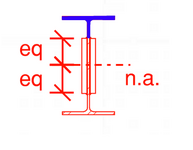
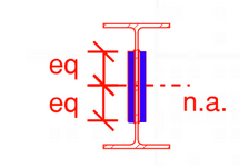
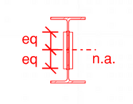
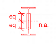
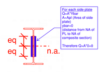
Let's say I need to use a web plate instead of a flange cover plate (I know...) to reinforce a beam. How do I calculate the required weld to ensure the section acts compositely? The shear flow equation gives the shear along a horizontal plane, but in this case, the faying surface is vertical. I can't quite wrap my head around it.


1751068113227.png
 

Attachments

  • 1751068099044.png
    1751068099044.png
    12.3 KB · Views: 5
This "diatribe" is relevant as it goes to the core of the original question.

The longitudinal shear flow between the plates and the I beam would be zero. All you need to do to have them act as a compositive section is to sister them together. So bolts or spot welds at the centroid would be sufficient.
 
This "diatribe" is relevant as it goes to the core of the original question.

The longitudinal shear flow between the plates and the I beam would be zero. All you need to do to have them act as a composite section is to sister them together. So bolts or spot welds at the centroid would be sufficient.
Shear flow between the I-beam and plates is not zero. Depending on the thickness of side plates, it may actually reduce the shear stress in the beam web for the height of side plates, but that is a questionable advantage since the shear stress in the remainder of the web remains the same as it was without side plates. So I see your point...side plates as shown in the original post are not useful. To sister the side plates is equally useless, so why not simply do nothing? Leave the I-beam alone.
 
Last edited:
Shear flow between the I-beam and plates is not zero.
I still disagree and have tried to make my point numerically, but have not had time for sketches or examples. Shear flow at that point may be non-zero, but shear flow between elements (in this case) is 0.

This has been shown numerically (see my previous post and sketch below)


Case I
1752242439255.png
This has been shown thru FEM - See detailed FEM approach above
This has been shown empirically via discussions about the two sections not being truly composite with examples such as comparison of Moment of Inertia and others.

There seems to be a basic disconnect on mechanics here and confusion between shear flow within the overall member at the top of the plate and shear flow being transferred to the plate. This topic is worth continued discussion as there seems to be some confusion on the topic and it gets brought up in here alot (although generally via a more"common member arrangement). Shear flow in the I shaped member at the top of the plate is not zero. But shear flow transferred across the joints to plates can be taken as zero as calculated above. BA - it seems like you are calculating shear flow as though the section is as below (full member joint at top of plat), but this is not the reality of the situation. Shear flow at the bottom of the WT "stays within" the W beam and is not transferred to the plates. (empirically, a section with a horizontal joint as shown below would behave differently than the web-plated beam above - and have more horizontal shear demand across the joint. It is my opinion that Case I would have no shear flow between elements and Case II would have shear flow across elements.

Case II
1752243954084.png
 

Attachments

  • 1752243944934.png
    1752243944934.png
    17.7 KB · Views: 0
Just thinking allowed. Immediately below the top flange, there will be a shear flow in the web. Progressing down the web, the shear flow will increase. As you get to the top of the two side plates, the shear flow will suddenly be confronted with three load paths, into the side plates through the two welds and down the web. If you take the shear flow in the web at the bottom of the welds (two vertical sides), will the thickness be the two welds and the web (V.Q/[I.(2.t+w)]? One or two have posted something similar.

Edit: the weld thicknesses could be at the 45 degree plane (min weld section).
 
Last edited:
I still disagree and have tried to make my point numerically, but have not had time for sketches or examples. Shear flow at that point may be non-zero, but shear flow between elements (in this case) is 0.
💙 THANK YOU! 💙

It has become quite circular and frustrating. But even then I've persisted because ultimately I have learnt a fair bit more about shear flow. You might have seen my grillage analysis that most people seemed to ignore. What was great about that was you could readily see shear flow, shear lag and it did improve my conception understanding.

There seems to be a basic disconnect on mechanics here and confusion between shear flow within the overall member at the top of the plate and shear flow being transferred to the plate.
Exactly.

It seems like some people have been blindly following text books and calculations for years without actually understand WHAT they are calculating.
 
Last edited:
It seems like some people have been blindly following text books and calculations for years without actually understand WHAT they are calculating.
Unless I am missing something, the numerical approach above does follow the "textbook" approach as far as I am aware; however it is not a case that is often covered in example problems for several reasons. It would have been a good"trick" question to throw in to a mechanics of materials textbook to push understanding of the concepts though..
 
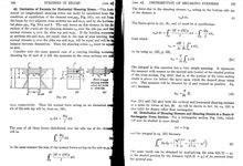
On the other hand, Timoshenko and MacCullough seem to be quite convincing in their text "Elements of Strength of Materials". Below is their derivation of Formula for Horizontal Shearing Stress.

Perhaps human909 could point out the fallacy in their reasoning.


1752263715152.png
 
Last edited:
Unless I am missing something, the numerical approach above does follow the "textbook" approach as far as I am aware; however it is not a case that is often covered in example problems for several reasons. It would have been a good"trick" question to throw in to a mechanics of materials textbook to push understanding of the concepts though..
Agreed. A fantastic trick questions judging by the discussion in this thread.

Though and certainly multiple ways to approach it. As many here have argued you don't even need to calculate it. The centroids are at the same point so sistering them would provide the same out come. No connection to allow shear flow required.

On the other hand, Timoshenko and MacCullough seem to be quite convincing in their text "Elements of Strength of Materials". Below is their derivation of Formula for Horizontal Shearing Stress.

Perhaps human909 or RWW0002 could point out the fallacy in their reasoning.
Why would you expect that I or RWW0002 would find anything there controversial? I'm the one who has constantly been linking the mathematical definitions.

The fallacy is in your leap of application to expecting welds are required to transfer shear in a location where the strain of the adjacent un-joined sections is identical. Or in other words, the shear flow (per section area) is already EQUAL in the absence of welds, so adding welds want change anything.***
***Like always, in this discussion of course vertical load needs to be transferred. Sistering with centroid bolts would be my approach.
 
Last edited:

Part and Inventory Search

Sponsor

Back
Top