Tek-Tips is the largest IT community on the Internet today!

Members share and learn making Tek-Tips Forums the best source of peer-reviewed technical information on the Internet!

  • Congratulations TugboatEng on being selected by the Eng-Tips community for having the most helpful posts in the forums last week. Way to Go!

Beam Reinforcement Calculation 2

Nick6781

Structural
Joined
May 15, 2024
Messages
55
Location
CA
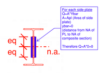
Let's say I need to use a web plate instead of a flange cover plate (I know...) to reinforce a beam. How do I calculate the required weld to ensure the section acts compositely? The shear flow equation gives the shear along a horizontal plane, but in this case, the faying surface is vertical. I can't quite wrap my head around it.
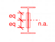


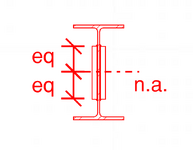
1751068113227.png
 

Attachments

  • 1751068099044.png
    1751068099044.png
    12.3 KB · Views: 5
This "diatribe" is relevant as it goes to the core of the original question.

The longitudinal shear flow between the plates and the I beam would be zero. All you need to do to have them act as a compositive section is to sister them together. So bolts or spot welds at the centroid would be sufficient.
 
This "diatribe" is relevant as it goes to the core of the original question.

The longitudinal shear flow between the plates and the I beam would be zero. All you need to do to have them act as a composite section is to sister them together. So bolts or spot welds at the centroid would be sufficient.
Shear flow between the I-beam and plates is not zero. Depending on the thickness of side plates, it may actually reduce the shear stress in the beam web for the height of side plates, but that is a questionable advantage since the shear stress in the remainder of the web remains the same as it was without side plates. So I see your point...side plates as shown in the original post are not useful. To sister the side plates is equally useless, so why not simply do nothing? Leave the I-beam alone.
 
Last edited:
Shear flow between the I-beam and plates is not zero.
I still disagree and have tried to make my point numerically, but have not had time for sketches or examples. Shear flow at that point may be non-zero, but shear flow between elements (in this case) is 0.

This has been shown numerically (see my previous post and sketch below)


Case I
1752242439255.png
This has been shown thru FEM - See detailed FEM approach above
This has been shown empirically via discussions about the two sections not being truly composite with examples such as comparison of Moment of Inertia and others.

There seems to be a basic disconnect on mechanics here and confusion between shear flow within the overall member at the top of the plate and shear flow being transferred to the plate. This topic is worth continued discussion as there seems to be some confusion on the topic and it gets brought up in here alot (although generally via a more"common member arrangement). Shear flow in the I shaped member at the top of the plate is not zero. But shear flow transferred across the joints to plates can be taken as zero as calculated above. BA - it seems like you are calculating shear flow as though the section is as below (full member joint at top of plat), but this is not the reality of the situation. Shear flow at the bottom of the WT "stays within" the W beam and is not transferred to the plates. (empirically, a section with a horizontal joint as shown below would behave differently than the web-plated beam above - and have more horizontal shear demand across the joint. It is my opinion that Case I would have no shear flow between elements and Case II would have shear flow across elements.

Case II
1752243954084.png
 

Attachments

  • 1752243944934.png
    1752243944934.png
    17.7 KB · Views: 0

Part and Inventory Search

Sponsor

Back
Top