StrEng007
Structural
- Aug 22, 2014
- 543
Got into a debate on this and would like some input.
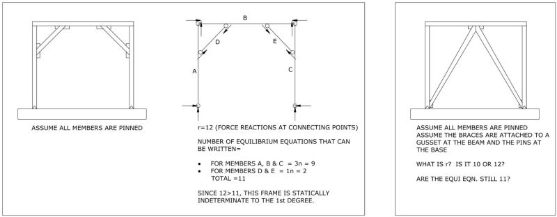
Using the general approach for determinacy on a FBD (r vs. 3n), I've presented two separate cases of a braced frame below. The first situation utilizes kickers that are located at frame corners. The kicker is assumed to develop an axial load only and only provides (1) equation of equilibrium as illustrated below. From what I see, this frame is statically indeterminate to the 1st degree. Is there any other way to quickly solve this 1st degree of indeterminacy without having to assume inflection points as we do using a portal frame method approach? Also, I don't want to consider a roller at one of the bases.
Using the same approach for counting the number of force reactions and equations of equilibrium, is the second frame unstable, determinate & stable or determinate & unstable.
NOTE: The horizontal beam is continuous in both examples. Each individual column is continuous in both examples.
Thanks!