Tek-Tips is the largest IT community on the Internet today!

Members share and learn making Tek-Tips Forums the best source of peer-reviewed technical information on the Internet!

  • Congratulations MintJulep on being selected by the Eng-Tips community for having the most helpful posts in the forums last week. Way to Go!

Grouted connection with shear keys in monopile - need a second opinion 1

Status
Not open for further replies.

drennon236

Civil/Environmental
Joined
Mar 27, 2020
Messages
102
Location
NO
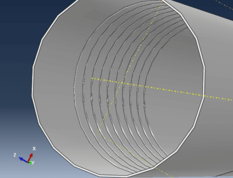
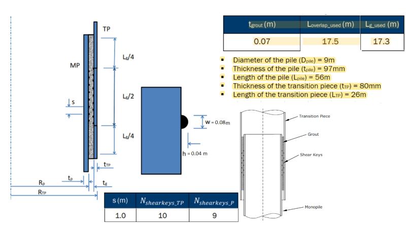
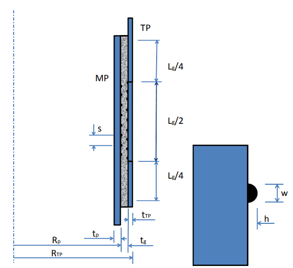
I am trying to make a finite element model of a grouted connection with shear keys in monopile:

111_vbysap.png


However, even though I can make a model I am not sure if its correct as I have no experimental data to compare with. I found a paper and design codes online and I am not sure which of these I should compare with (or if there is even any point in comparing the data), and would like to hear a second opinion.

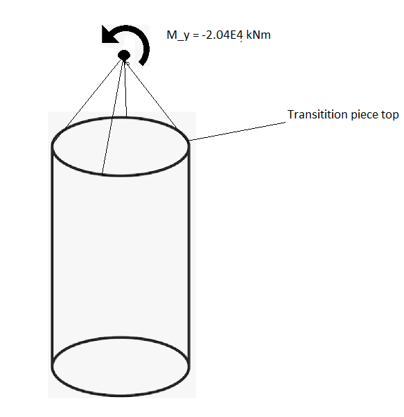
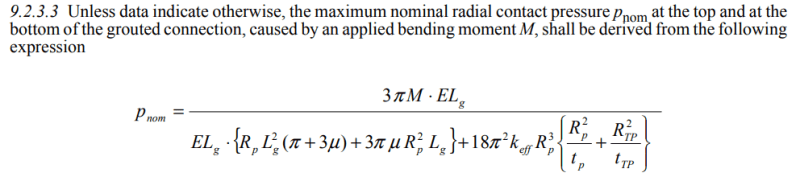
Could I apply a bending moment to my model and check if the maximum nominal radial contact pressure at the top and at the
bottom of the grouted connection is the same as the output from the model? - would this make sense to confirm the accuracy of my model?

111_rv24tw.png


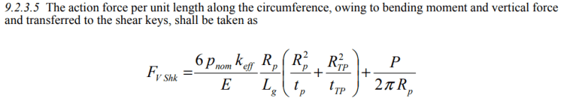
Can I use this for comparison - find spring "action force" model and see if its the same as the equation?

111_q90z4r.png
 

You could apply a bending moment to your model ..but looking for the maximum nominal radial contact pressure at the top and at the
bottom of the grouted connection will not be reasonable approach.

Consider the joint as a cylindrical tube, the axial force resistance developing will govern..

Simply ,you may transfer the moment to a couple and try to find the bearing stress transfer thru the beads.

What about the beads? Weld bead ?..
 
Im sorry but could you expand on what you mean? I am not sure I follow, ill try to give my understanding.

- I look at the entire joint as one cylindrical tube and dont consider the contact inbetween the parts. The axial force will be governing, when I apply the moment I should check for the axial force resistance, but how can I know what axial force I am supposed to get from the applied moment, is there an equation?

- Do you mean I should apply moment and see how its transferred to the shear keys or beads? So apply moment and look at what stress develops in the beads?


"What about the beads? Weld bead ?.."

Is there a way for me to use weld beads (shear keys) to confirm my computer my model is correct? Maybe just look at the weight of the cylindrical tube and see if the weight is carried entirely by the weld beads/shear keys?


In order to see the analogy, consider only axial load is transferred . The axial load will be resisted with bearing of grout and the bearing area will be the horizontal bead surface with grout and the grout will only resist compression stresses.
With this approach, if you limit the bearing stress of the grout, you can calculate the no. of bead rings.

In case of pure moment, if somebody model the moment with a couple applied to grout ring , IMO, acceptable. Say, the dia 50 in. and the moment 1000 kips-in. The couple force C= 1000/ (0.8 *50)=25 kips and arm =40 in. The couple force will be effective for a crescent part say with a length = 3*50/6= 25 in.

You may refine the approach the moment will be resisted with a ring and find the max fiber stress through the lap length.


Your picture implies weld bead. The beads can be weld bead, round bar with fillet welds , flat bar with fillet welds.

P.S. The allowable bearing stress shall be limited 20 psi for service loading and grout strength shall be limited fcu ≤ 16,000 psi


The shear keys look something like this, they go along the entire circumference:
Take1_3_tuapwe.png


So the axial load will simply be carried by the shear keys, I can measure the load the shear keys are carrying and see if it makes sense (make sure it takes all the self weight and potential axial load).

Would it be possible for you to do a simple drawing of the second part of your explanation with the pure moment applied? It would be very helpful in understanding.
 
Those equations in your first post, what publication do they come from?
 
I can't really comment on the bending aspect of this, but a good analogy for axial load transfer would be something similar to how the deformations on rebar react against the surrounding concrete. For whatever that's worth...
 

Dear drennon236 ;

Use the famous bending formula.. f= M/ W ( W section modulus of the circular grout section ) find the max . stress and multiply with grout thick. You will find the force column. Then divide 20 psi and find the bead area required, then divide to bead thick. ( h with your notation ) and find the no. of beads.

For more info. give all the dimensions (pipe dims, thicks, grout thick, bead dims), the applied moment and the software that you use.. good luck...
 
Dear Retrogade: its DNV-OS-J101 - Design of Offshore Wind Turbine Structures - Section 9.2.3.
link below:

Dear HTURKAK:

I use Abaqus CAE, and moment applied can be anything, but lets say -2.08E4 in the y-direction. The loads in this model (moment, concentrated force etc)is applied to the transition piece top, it is applied to a top point which distributes the moment averagely across the top (structural distribution).
skjermbilde2_zztmtj.png


Dimensions are shown below.

Skjermbilde_frabqh.png
 

Dear drennon236 ;

Lets check your dimensions ;
Sleeve geometry = Ds /ts = 9000/80 =112.5 ?? should be less than 80,
Pile geometry = Dp/ tp = 9000/ 97= 93 ?? should be less than 40,
Grout annulus geometry = Dg/tg =9000/70=128 ?? should be less than 45
Shear key shape factor = w /h =80/40=2 O.K.

You provided a nominal moment My= 20400 kN -m , and assume a axial load W = 50000 kN.

The max. shell compression force at transition piece Nc= W/(Pi* D )+ 4*Md /(Pi*D**2) =50000/pi*9.3 +4*20400/pi*9.3**2 =1711+300 = say 2000 kN .

the nominal allowable axial load transfer stress for the grout fba= 0.138 + 0.5 fcu*h/s=´0.138+0.5*40*40/850 =0.95 MPa

No of shear key required= 2000000/1000*40= 50 no's You are expected to provide 50 shear key for transition piece and 50 shear keys for monopile. The shear key spacing could be 300 mm .. in this case, the overlapping length will be 15000 mm.

This is a preliminary calc. based on nominal loads and i did not check for calculation mistakes..

I will suggest you to look API RECOMMENDED PRACTICE 2A-WSD (RP 2A-WSD) Commentary Section C.7.4.4d.

You are free to perform finite element analysis with abaqus but your design should be based on calculations which are verified with tests.
 
Dear Dear drennon236 ;

This thread regarding the grouted connections of monopiles is not a common thread. When you decide upon your final solution for the analysis model , please share your solution for record and to help younger fellows and keep us involved..

I have written my respond for the preliminary calculation without looking to DNV-OS-J101 - Design of Offshore Wind Turbine Structures - Section 9.2.3.

I just want to remind also , it is polite to answer when you get a respond.


Kind regards..
 
Status
Not open for further replies.

Part and Inventory Search

Sponsor

Back
Top