Continue to Site

Eng-Tips is the largest engineering community on the Internet

Intelligent Work Forums for Engineering Professionals

  • Congratulations waross on being selected by the Eng-Tips community for having the most helpful posts in the forums last week. Way to Go!

Z-direction Plate for Offshore Structures 1

Status
Not open for further replies.
Jun 25, 2019
6
Dear Colleagues,

Why do we use z-plate in lifting padeyes of offshore structures?, What is the physical phenomenon? Why do not we use this in End plate connections (static structures)?

thank you
 
Replies continue below

Recommended for you

Danielborgesdefreitas:
Give us a hint…., what are ‘Z-plates in lifting padeyes?’ Show a reasonably well proportioned sketch, with some of the needed design info., and you might get an answer.
 
Because they are cheap and efficient, and we do use this in our pin jointed heavy structures like mine headframes.

Did I guess the question right?
 
Danielborgesdefreitas:
Get out your Engineering Mechanics and strength of Materials, which you used while you were getting your engineering or tech degree, and start studying them for the answers, and we’ll help, once the questions are not first semester engineering or tech school questions. Are you actually a Structural Engineer, or what? What are the load paths and how do the loads get from the crane to actual load being lifted? What kinds of loads, what kinds of stresses, etc? Draw some FBD’s (free body diagrams) showing the loads and stress fields in the various parts. I assume the lifting beam has some depth (width) in/out of the page, and some length; show a plan, side and end view, with some indication of the load. I wouldn’t call what you show a “Z” pl., it is just a simple padeye or lifting pl. with a hole for a lifting shackle, which will take a sling or hook from the crane. The lifting pl. has several doubler pls. (doughnuts, with matching holes) to provide improved pin bearing at the pin hole and to distribute that concentrated reaction stress out into the lifting pl., how does this work? It attaches to the top of a beam which will span out, basically as two unbraced cantilevers to pick up the load. How does this beam work at all load points? You would do well to get a copy of the ASME BTH-1 Std., “Design of Below-the-Hook Lifting Devices.” It is one of the primary stds. which govern the design of this type of equipment. Do some reading and FBD sketching and show the loads and load paths of the various parts here, with some of your questions and we can go further.
 
My answer stands. Mayo Tunneling and Mining Equipment built us a mining headframe using square HSS with pin connections at their ends. The pins were at least 6-inches in diameter and driven home with large hammers and larger iron workers. It was shop assembled prior to shipping and erected alongside Riverside Drive in NYC back in the early '70s. It went up in an afternoon, lest the locals become vocals.
This was for the Interceptor Sewer tunnels for the North River Water Pollution Control Project.
 
I think the OP might mean 'Z' through thickness tested plate right?

You use this where there is a concern from lamellar tearing occurring, this can be issue with thicker plates, and/or plates where the load is through the plate in the Z direction perpendicular to the face and there is a lot of restraint form the welding process.
 
Agent666:
Actually, as I finally reread it, “Z-direction,” I suspect he/she is talking about their model coordinate system, with the “Z” pl. standing up, as his lifting lug is, while the X-Y plane contains the beam plan view. Lamellar tearing is so far out of the realm of things at this stage as to muddy the waters. Let’s figure out how a basic lifting lug works first. Let’s see if he comes back having given the problem a little more thought and self study.
 
I guess we'll see if the OP gets back to clarify, but Z grade through thickness tested plate made more sense to me based on the question relating to the lifting eye and comparison to moment end plate connections that don't necessarily use Z plate.

Capture_vgzkep.png
 
For the record, I understood the question to be the same as Agent666. Maybe an antipodean thing. But it tallies with the confusion in the initial post as to why a padeye needs Z-plate (no Z load) but not end plates (big Z load) - as Agent said.

Z-plate is also common in offshore because of the nature of the connections and the cyclic loading.
 
"Z" plates refer to plates which have had additional tested for 'through thickness' properties. The testing is broken into three quality classes (Z15, Z25 and Z35), details of which can be found in BS EN 10164.

These are commonly used where a padeye plate in the vertical plane is welded to a plate in the horizontal plane (think at the top of a column with a cap plate, with the padeye plate welded on top).

Z plates are tested to ensure there are no (fewer?) material defects which may result in delamination of the steel (lamellar tearing) when the vertical component of the padeye load is passed through the thickness of the column cap plate (and reacted by the column weight on the opposite side of the cap plate), resulting in tension applied through the thickness of the cap plate.

Through thickness properties are often also required for heavy joints (particularly moment resisting cruciform joints) where flanges of incoming members may apply significant tension through the flanges of the receiving member and into back up stiffeners etc.

For more info. see BS EN 10164 and associated docs.
 
dear Dhengr:

Why End plate (moment connections) with flanges have the effect of lamellar tearing as Design Guide 4, and we don’t use z-plate? For example, padeyes of structures offshores always is required z-plate. For verification of flanges is only required the yield strength (fy) and tensile strength (fu).


Reference:
Design Guide 04 - Extended End Plate Moment Connections

Chapter 1

d)End plates are subject to lamellar tearing in the region of the top flange tension weld.

 
 https://files.engineering.com/getfile.aspx?folder=869d599e-7258-4dba-8a56-e001d335711f&file=end_plate_or_padeye.png
Don't know why Z quality steel is used for padeyes, however it certainly is a good idea to use it for thicker base plates.
You don't have the sulfides (MnS) in thinner plates as severely as in thicker plates, that cause the delaminations. You judge where "thick" plates start, based on the mill test certificate.

vrijgegeven_rpawvf.jpg
 
Just to clarify it isn't the padeye plate itself which would be Type Z, but the plate it is attached to. Exactly the same idea as kingnero's situation - padeye plate is the vertical plate, and cap plate (which attaches the padeye to the structure being lifted) is the horizontal plate.

Obviously it is not applicable to some situations where the padeye doesn't attach via a cap plate...
 
Danielborgesdefreitas:
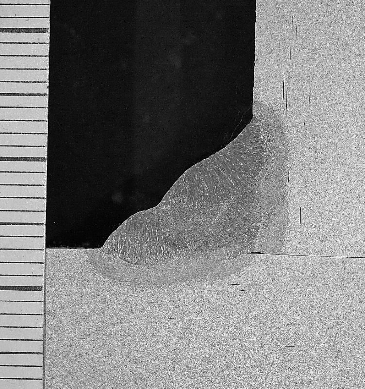
And, now I know what Z-plate is. Sorry for the misunderstanding, in my old age, I did not know that exact terminology for that plate testing. I guess we always just called that through pl. thickness testing and properties. I haven’t mill ordered any steel lately. I do not understand the need for that criteria in a padeye pl. and do see the potential need for that criteria in the end pls. on an end pl. moment connection. So, I now understand your question, and agree with your thinking. I would not want laminations in either pl., or significant slag inclusions, and we often tested for these when it was important or critical. We could order that this testing be done, at the mill, on our P.O’s, at an extra cost. That seems to be what you are calling Z-pl. You can usually see laminations and larger slag inclusions when you are cutting the material and run into them. Kingnero’s photo shows some very small inclusions of one sort or another. Weld details and defects are usually much more important/critical as relates to a quality fabrication.

In the padeye pl. detail the primary stresses are parallel to most/any laminations or inclusions, so small inclusions would not usually be a problem, and large laminations (which I wouldn’t want in my fab.) would almost be akin to two pls. with a faying surface at the lamination. In the end pl. detail, the stresses are obviously in the “Z” or through-pl. direction and a lamination is critical. In very rigid, stiff or restrained connections/joints the residual stresses from welding heavy welds and the like become very high, and are tri-axial in nature, thus the lamellar tearing occurs. I don’t like codes and design guides calling this stuff out (or not), this way. I would sooner my engineers understood the reasons behind the issues and automatically designed around these potentials, using good engineering judgement and experience. But, the way the code writing business is going these days, they want any dummy to be able to do it, if only, they have some software and they can read the code (cookbook) and follow it to the letter. There’s no need to really understand what they are doing, or the rationale behind the code requirements, just follow the formula and directions. After all, many of the code writers can’t explain the origins or rationale behind the requirements either. Over the years, as the codes became more complicated, I’ve suggested that the various code authorities should have a full time engineer, as a historian, recording and documenting the line of, and reasons for, code changes, so that people could better understand the origin, rationale and intentions of the codes. There’s no money in that when you are running a publishing business, selling new editions, instead of a knowledge based, industry wide, information and knowledge provider to the design community.

For years the steel industry kinda hid these issues. They knew that inclusions and piping existed in the web/flg. “k” regions of rolled shapes, and the more so in heavier sections, where larger ingots were needed for the rolling. With pls., they didn’t like, and warned against, ripping pl. down the mid-pl. width region, because of the potential of finding laminations. The rolling process tends to concentrate these defect/flaws in these areas. The world was generally oblivious to these issues because the primary stresses in these products, in use, were parallel to the defects, and caused very few problems. As much more complex details, restrained connections and welding have proliferated, these issues have required more attention to details of design and fabrication. Some of these material deficiencies should be being reduced with the advent of the continuous casting process in the making of steel.
 
1: before loading, purely because of shrinking stresses
2: yes
 
The Steel Construction Institute Guidance Note 3.02 is worth reading. Free on the internet.

I have a document from the 1970s that says lamellar tearing was unknown due to in-service loads - neither initiation nor propagation. It was seen entirely as a welding issue.
 
Status
Not open for further replies.

Part and Inventory Search

Sponsor