Tek-Tips is the largest IT community on the Internet today!

Members share and learn making Tek-Tips Forums the best source of peer-reviewed technical information on the Internet!

  • Congratulations cowski on being selected by the Eng-Tips community for having the most helpful posts in the forums last week. Way to Go!

Whitmore Section for Gusset with Staggered Holes

Status
Not open for further replies.

phamENG

Structural
Joined
Feb 6, 2015
Messages
7,744
Location
US
Question about the Whitmore Section when designing a new or checking an existing gusset with staggered holes:

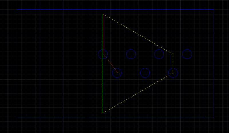
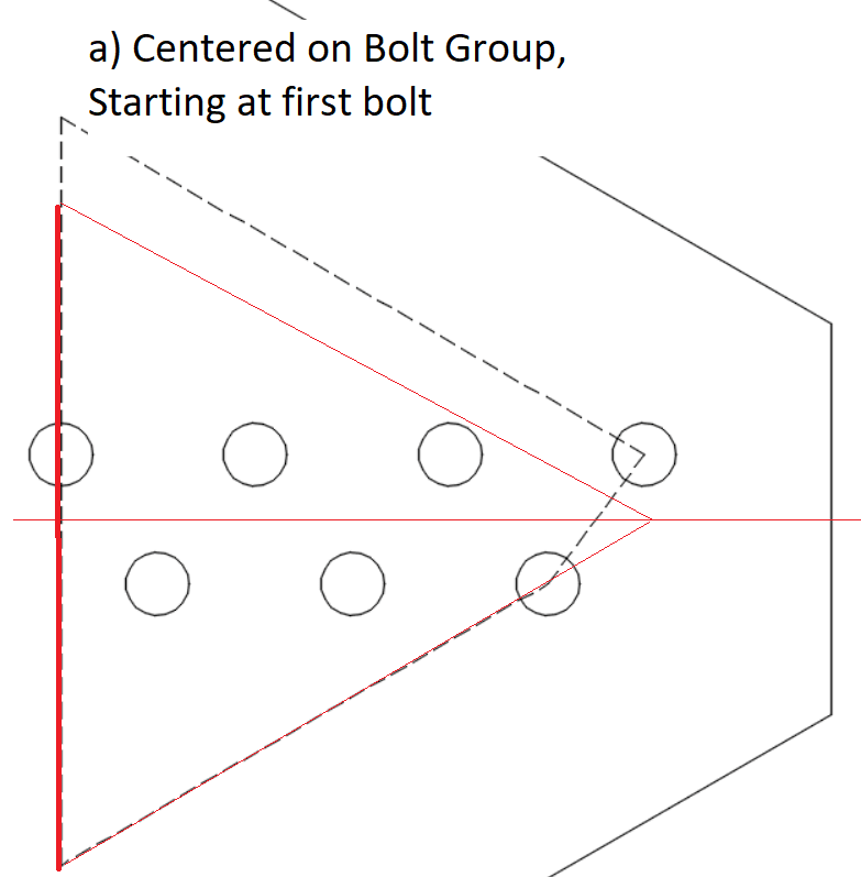
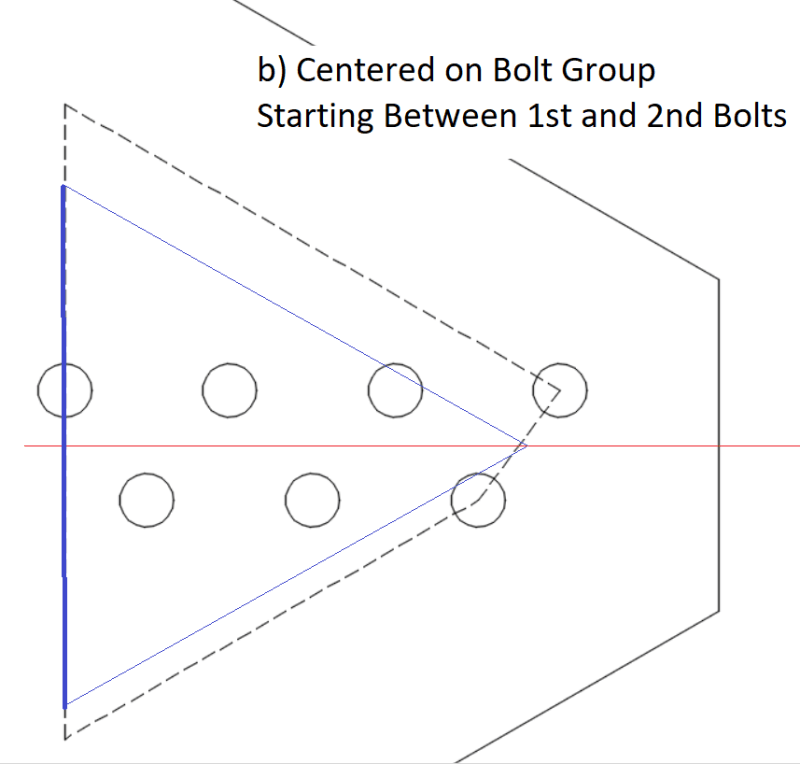
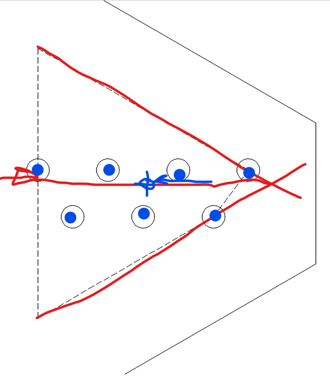
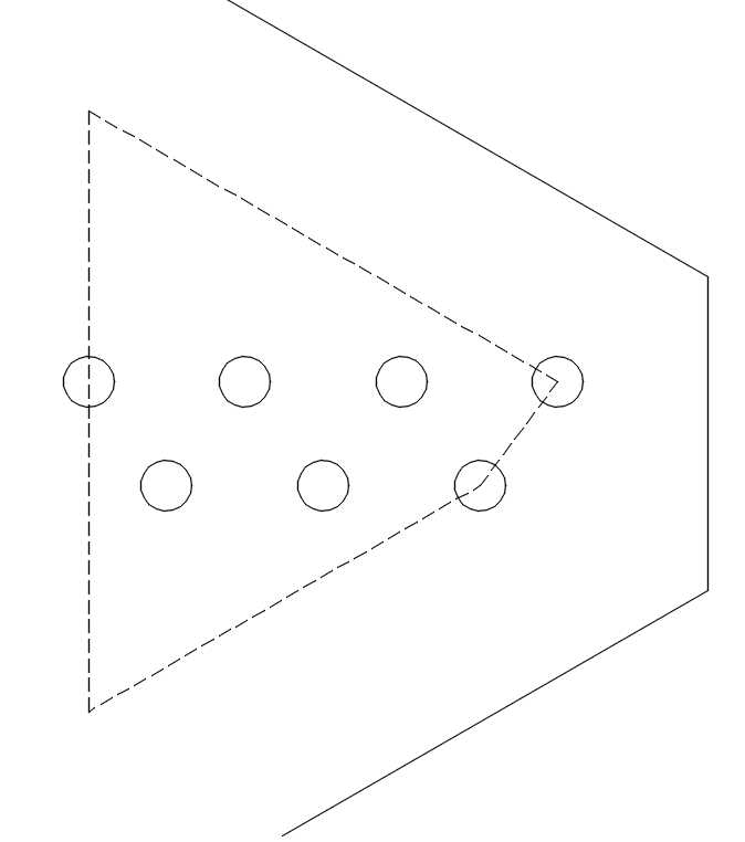
How do you determine the "top" of your Whitmore - do you draw your 30 degree projection from each of the leading bolts and connect them through the last? See attached sketch.

My only concern with this is that the resulting center of the area at the base of the block is skewed from the centroid of the bolt group. Not sure if this concern is legitimate, though - I just like it when things line up.


staggered_whitmore_epf12o.png
 
I thought a little more, and I think this is probably the way to go. The green and red lines (offset for clarity) indicate areas to check for rupture in the net section in tension. In compression, the distance from the inner bolt hole (the one that has the red line passing through but not the green) to the connected edge of the gusset would be a conservative estimation of unbraced length for the "middle" of the Whitmore.

Any agreements/disagreements? Thanks.

staggered_whitmore2_vs3yfa.png
 
This is a great question. Unfortunately, I don't have any definitive answer for it. What you have shown seems reasonable, unless someone else can show published data to support a different approach.

Alternative choices that also seem reasonable and are more conservative.
a) Expand out the whitmore section based on the length from the first bolt. But, keep it centered on the bolt group and symmetrical. I believe this will give you a smaller whitmore section. But, one which is centered.
b) Do the same thing, but start halfway between the first and 2nd bolts.

image_pneuac.png

image_j3y4om.png
 
I agree more vigorously with your 2nd post. Actually, for compression I think this will present a very similar whitmore section to my option a).
 
Thanks, Josh. I appreciate the input. I did find a paper that states "The Whitmore section...is established by drawing two 30-degree lines form the center of the last bolts to intersect a line passing through the first bolt line and perpendicular to the axis of the member." That works well if your bolts are aligned or you have an odd number of staggered bolt lines, but seems a bit ambiguous in the situation I've presented. Seems like my second post is, at worst, a conservative interpretation of this definition.
 
I don't see the issue. Either the brace or the gusset shall withstand the moment caused by eccentricity. The Uniform Force Method is basically dealer's choice game, and it works because we're dealing with approximations and inequalities. Choose the simplest path.

The blue line can be at the bolt centroid or the brace centroid.
image_b3dunz.png
 
Rick, overthinking is what I do. It helps account for a personal insecurity - the fear of underthinking.
 
Status
Not open for further replies.

Part and Inventory Search

Sponsor

Back
Top