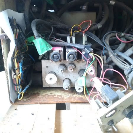
This is a custom made valve block.
It’s the hydraulic equivalent of a PCB in electronics.
To design such a block a hydraulic schematic is first created based on the specific needs for a particular machine, then valves are selected and physical layout made.
Thousands of cartridge valves (“screw in valves”) with various functions and sizes are available to choose from from dozens of suppliers as well as cetop valves (the ones screwed on). After this a block is machined with cavities for all the valves and the connection channels between them. Blocks range in size from a pack of cigarettes up to several tons. The function of one of these custom made hydraulic blocks can be anything you can imagine. New designs are being created everyday around the world.
This is why you can’t find much info online.
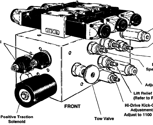
If you want to understand how this particular block works you start with the schematic (which I believe you have). Redraw if necessary for clarity. Print it out and get your colored pens out to trace lines through the valves in different states (hoisting, lowering, turning etc.).
Make sure you identify all components on the schematic in real life and vise verse. Usually this is enough to get a good understanding.
If needed, the next step would be to identify the brand and model of every single valve and download the datasheets.
If you post a high quality version of the schematic I may be able to help you out.