chez311 said:
What is the meaning of (x,y) coordinates of an axis with orientation error*?
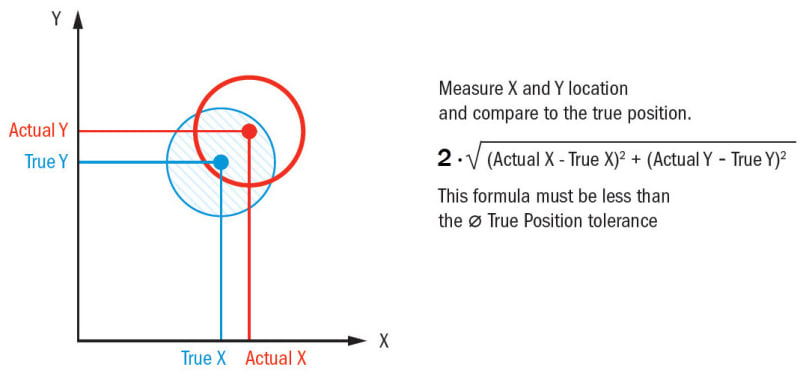
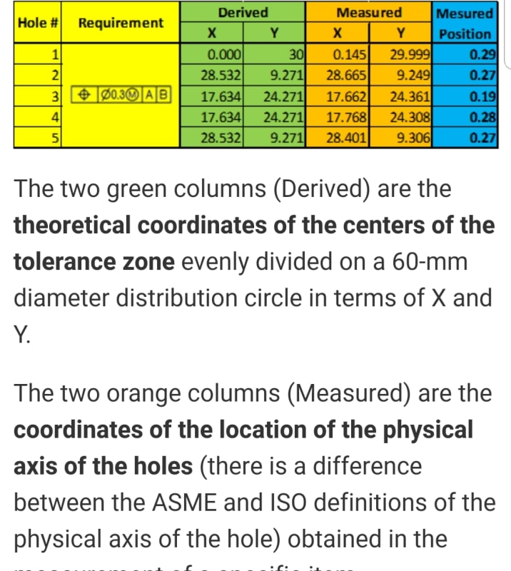
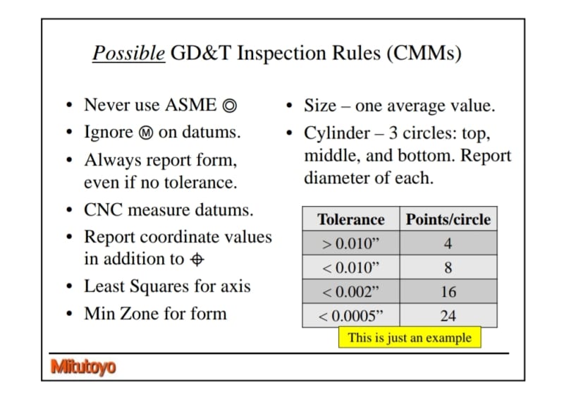
I've been asking myself the same question. But recording, and usually also reporting the measured coordinates is how I've seen this done and taught in various sources. A few examples are:
An explanatory figure from gdtbasics.com:
A suggested measurement report from a tip on some other GD&T training website (It can be argued that this source is unreliable as they suggest validation according to axis interpretation for an MMC tolerance specification):
A more reliable source is CMM measurement guidelines from Mitutoyo. Notice the part that recommends/guides to report coordinates in addition to the actual value of position.
chez311 said:
the actual value doesn't care where your origin is. These calculations can take place no matter where the arbitrary origin is taken from, as long as its consistent between measurements, it makes no difference.
The point was that while datum feature simulator C in YuYu28's figure is good enough to constrain the translational degree of freedom in the horizontal direction (parallel to datum plane B), it is a bad reference to set a zero on, for coordinate measurements in that same direction. Perhaps one could use as a reference a fixed point/line element along this slanted plane simulator, for example at a distance of 130 from the theoretical location of the true position, and set a zero there, but I don't know how practical that is. Perhaps someone with inspection experience can share their insight.
Another option could be to convert the horizontal locating dimension 99.03 to a dimension at the direction perpendicular to the C datum plane. The other locating dimension- 11 is perpendicular to B so the two "coordinate" dimensions for measurement become non-perpendicular. This is probably troublesome too. Even when Y14.5-2009 describes the "Rectangular coordinate method" (7.4.4.1) it specifies that:
"The feature control frames are attached to dimension lines applied in perpendicular directions." I assume that the perpendicular directions requirement is from practical reasons as any coordinate system is based on perpendicular axes.
So the only practical choice left seems to be using an "arbitrary origin" instead, but then - again, you are not avoiding the "inspection equipment touching theoretical features" argument that you brought up. Datum feature simulator C will not be the direct reference. It will be necessary to set a zero on a theoretical origin, one that is not directly tied to a datum feature, i.e. not a datum feature simulator.
Nevertheless, using the physical edge as a measurement origin is not a theoretically valid option, from the reasons we both mentioned. Unfortunately, it is an option that manufacturing might push for in order to avoid complicated gauging (that is according to my experience). It is good for Yuyu28 to be aware of these issues in order to be ready to cope with them.


