SwinnyGG: "None of us are going to spend an hour working up a detail in CAD for you,"
Why would you think that I would need you to do that? Have I not shown myself perfectly able to produce my own CAD in response to eevry question?
SwinnyGG: "The one thing you need, as far as I can tell, is a solution to the problem of integrating a bearing cage into your edge-located thrust bearing. This is not really a difficult thing to do. One of your parts has to grow, sufficient that it has enough material for an internal volume to accommodate a bearing cage. "
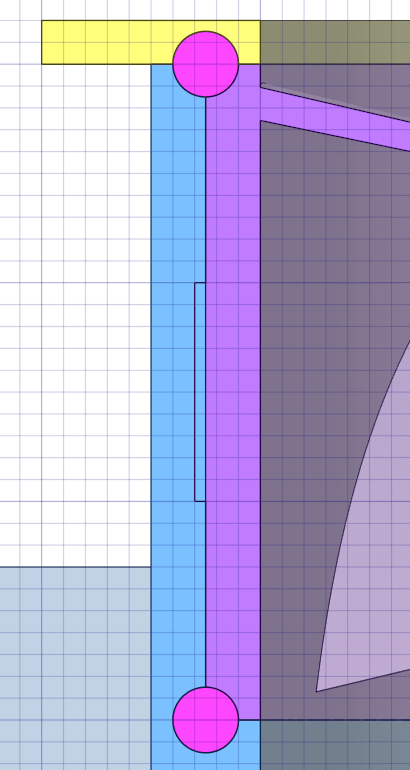
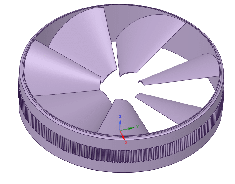
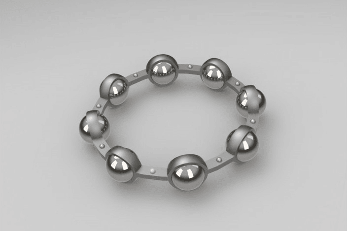
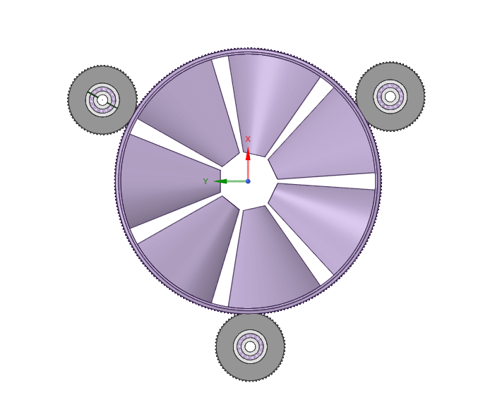
I assume you mean something like this:
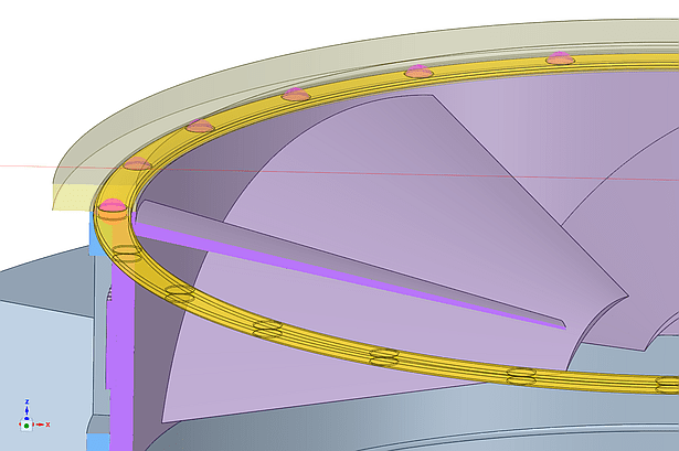
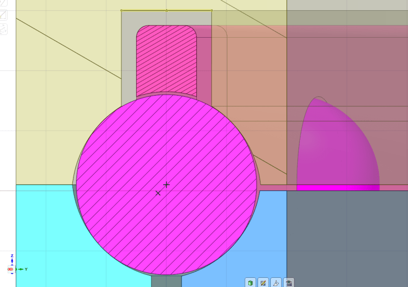
Let's look at that idea in detail:
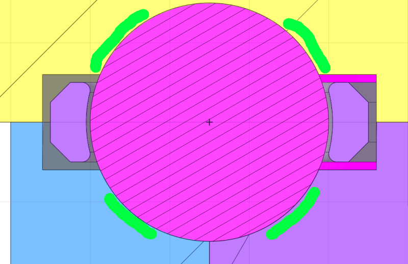
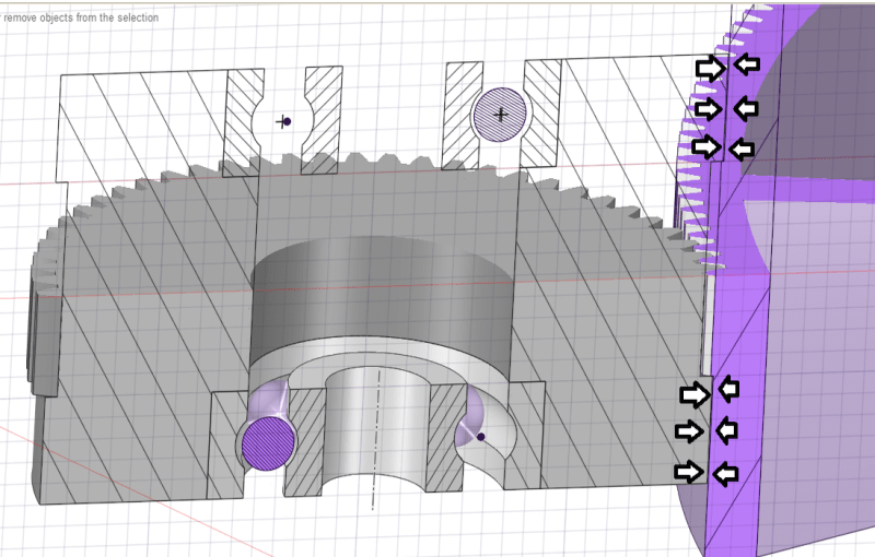
In order to support the load both radially and axially, it will be necessary to retain material in the raceways at diagonally opposed areas as highlighted in green above.
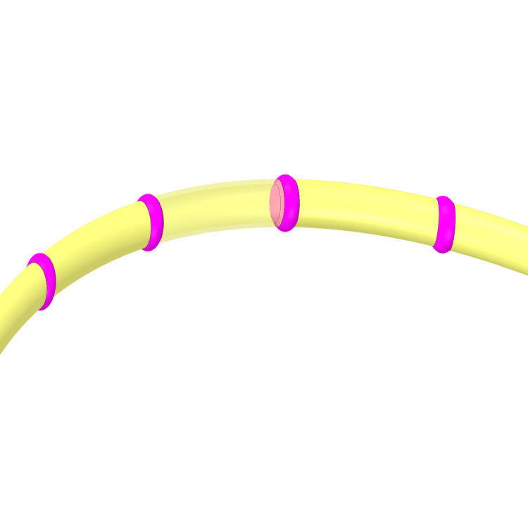
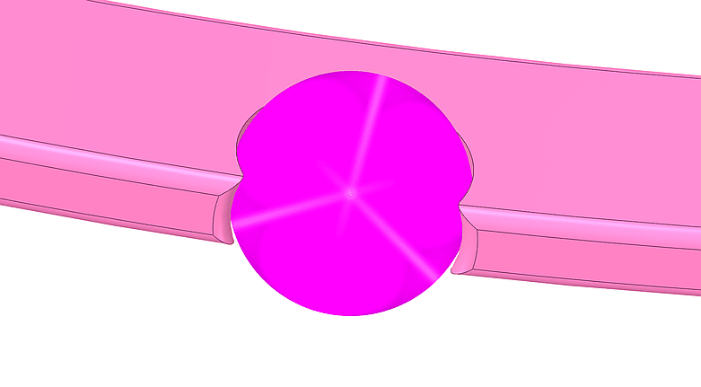
And that places an upper limit on the thickness of the cage, so it ends up looking something like this:
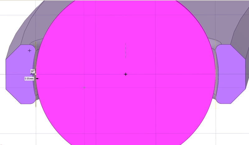
Can you see the problem yet?
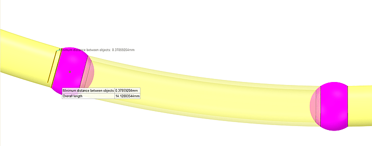
If you make the clearance sufficient to prevent high friction in use, the hole is too big to retain the balls.
0.05mm (a gnat's under 2 thou if you are of that persuasion). I cannot 3D print any tighter.
And if I could, how would I get the balls in to the cage?
I guess if I had the equipement at home to produce a 2-part, pressed phosphor-bronze cage and rivet them together something like
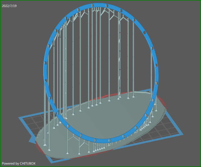
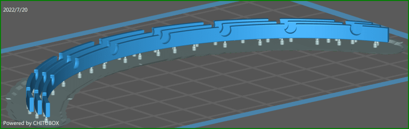
I might be able to make it work; but I have to live in the real world where 3D printing a 1mm thick, 4mm wide, 120mm diameter ring like this fraught with problems:
Even if I could make the hole tolerences tight enough to retain the balls, the idea that I would be able to get something as large, thin and delicate as that to print correctly is inconceivable.