Dear shettyp,
This is a complex matter, I run fatigue analysis in welds using winLIFE and I can tell you that the meshing approach to use is dependent of how you plan to mesh your structure using 3-D solid or shell elements, and of course, of the model size:
• In the case of solids you can mesh "explicitely" the seam weld, then you need to create in NX the geometry for the seam weld and mesh like another part assembly. For accuracy reason HEX meshing is preferred.
• In the case of Shell meshing then you can ignore or not the seam weld, it depends of the dimensions of the model, for accuracy reasons 4-node shell CQUAD4 elements are preferred, do not use triangular elements at all. The use of 8-noded elements is recommended particularly in case of steep stress gradients. In a plate or shell element model the elements have to be arranged in the mid-plane of the structural components.
Here you are the recommendations of the INTERNATIONAL INSTITUE OF WELDING (IIW):
In simplified Shell models,
the welds are not modelled, except for cases where the results are affected by local bending, e. g. due to an offset between plates or due to the small distance between adjacent welds. Here, the welds may be included by vertical or inclined plate elements having appropriate stiffness or by introducing constraint equations or rigid links (RBE2 element) to couple node displacements.
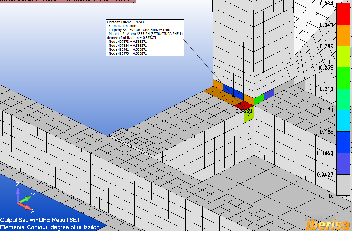
Here you are an application of Shell meshing for fatigue analysis on welds using the Hot-Spot Method where the welds are not modelled, but the seam weld is automatically identified:
The Fatigue Damage results can be plotted back in the FEM postprocessor:
Here you are a video in my Youtube channel where you can see how to perform a Fatigue Analysis on a 3-D solid asembly when welds are meshed with 3-D solid HEX elements:
Well, fatigue analysis in welds is complex, but I hope you have now an idea of what we can do using FEA, OK?. In the above examples FEMAP with NX NASTRAN together with winLIFE were used, but importing FEA Stresses results from NX AdvSim + NX Nastran is possible as well.
Best regards,
Blas.
~~~~~~~~~~~~~~~~~~~~~~
Blas Molero Hidalgo
Ingeniero Industrial
Director
IBERISA
48004 BILBAO (SPAIN)
WEB:
Blog de FEMAP & NX Nastran: