Oasis Design
Civil/Environmental
Hello,
I hope this message finds you healthy and well.
I’m helping with the design of a long water line for an improverished non-profit in the high desert in Southern California.
I have good general water design skill but little specific water hammer expertise. Would you be willing to give the design a quick sniff test for them, and maybe point us in the right direction if we’re way off of the reservation?
If so…here you go—
• There’s 4300' of 2" buried DR-17 HDPE tubing, followed by 9000 of 1" buried DR 11 tubing.
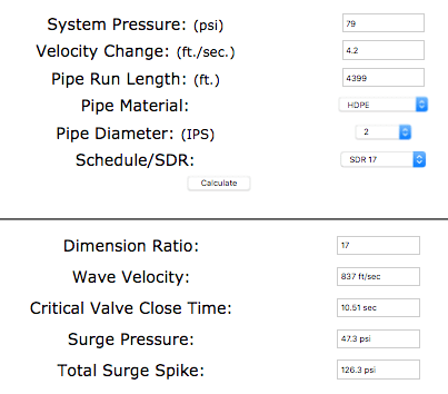
• The max flow velocity in the 2 in is 4.2 ft/sec, in the 1" about half that, so the 2 in seems like the more critical application.
• The line runs down a 2%± continuously sloping valley. The max pressure in the 2” (which is PE4710 rated at 130 psi) is 79 psi, as it carries on in the 1” (PE4710 rated at 200 psi) it reaches 126 psi in the low end.
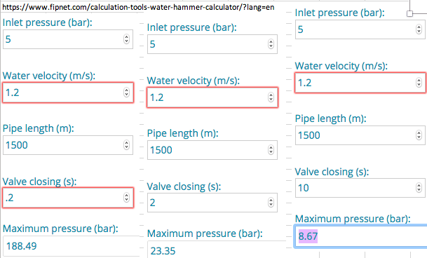
• Is there even a problem, or is the the nature of P44710 resin to just take sudden velocity changes in stride?? PE4710 resin in DR17 can take a 5.6 ft/ sec recurring sudden change in velocity, and 11.2 ft/sec occasional sudden change in velocity, according to On the other hand, online calculators suggest pressure spikes of >1000 psi and valve closing times of 10 seconds (screen shots below) what gives??---more detail:
• Most joints are to be fused, with some compression fittings at the transitions to galvanized above ground taps, and some fused transition nipples to pipe thread where water hammer is most likely.
• The system alternately freezes and fries, with 50°F temp swings every day.
• There's not much money for the install (it's only happening because of a grant) and maintenance can be iffy.
• All the regular operation valves are hose bibs where a handle needs several twists to stop the flow.
My concern is the drain valves on the 2", which are brass ball valves that will generate max, open discharge velocity when open, and could be closed in a fraction of a second by inexperienced operators.
I wonder too what happens when the drain at the very end of the 1" opens, and 4300' of 2" water battering ram adds to 9000' of 1" battering ram; can't quite picture this.
Online calculators suggest a valve close time of 10 seconds.
Here’s what I’m thinking of doing to mitigate:
• Put big signs on every valve saying to take 10 sec to close valve to prevent system explosion
• Pressure relief valves, possibly everywhere there’s a valve (there's about 15). A bit nervous about freezing, but this seems cheap and easy...is this effective?
• Air reservoirs in blind-ended uphill pipes, teed off the system at drain valves, of the same material in the same trench, sloped uphill so they’d catch air and hold it (and also drain when the valve was opened.) I’m guessing 20-50' of 2" in tubing at each of the two drain valves? This would be inexpensive and low maintenance. The cap at the end would be fused, so unlikely to leak. These could be spliced in anywhere there is a valve, so there would be shock absorbers everywhere. They would only be sloping about 2%, like the ground, though they could be sloped more in the trench as we’d not be so concerned about freezing or traffic. ANY GUIDANCE ON SIZING THESE? We could make them as long as we want. I realize these will slowly fill with water, but they can be made so they will drain when the system is drained every year or two.
• Bladder tanks—worry about freezing, maintenance, cost
• We could replace the ball valves with twist handle valves…but these would be especially problematic for the drains
• I wonder if the nature of HDPE will save us, by expanding as the pressure spikes then relaxing.
• Perhaps the compression fittings may pop off the ends of the HDPE at transition to galvanized, providing a softer failure mode than the pipe exploding (water is fairly abundant, so losing a tank of water would not be as bad as the line breaking)
• We're planning on going with DR 17 for the 2" line, rated at 130 psi, rather than DR 11, to lower cost and the amount of plastic (this saves $1300 and 2,000 lbs of plastic). This is a bit non-conventional, but fits the strong environmental ethics of the place. According to the online water calculators
Thoughts?
Thank you!!!
Art Ludwig
I hope this message finds you healthy and well.
I’m helping with the design of a long water line for an improverished non-profit in the high desert in Southern California.
I have good general water design skill but little specific water hammer expertise. Would you be willing to give the design a quick sniff test for them, and maybe point us in the right direction if we’re way off of the reservation?
If so…here you go—
• There’s 4300' of 2" buried DR-17 HDPE tubing, followed by 9000 of 1" buried DR 11 tubing.
• The max flow velocity in the 2 in is 4.2 ft/sec, in the 1" about half that, so the 2 in seems like the more critical application.
• The line runs down a 2%± continuously sloping valley. The max pressure in the 2” (which is PE4710 rated at 130 psi) is 79 psi, as it carries on in the 1” (PE4710 rated at 200 psi) it reaches 126 psi in the low end.
• Is there even a problem, or is the the nature of P44710 resin to just take sudden velocity changes in stride?? PE4710 resin in DR17 can take a 5.6 ft/ sec recurring sudden change in velocity, and 11.2 ft/sec occasional sudden change in velocity, according to On the other hand, online calculators suggest pressure spikes of >1000 psi and valve closing times of 10 seconds (screen shots below) what gives??---more detail:
• Most joints are to be fused, with some compression fittings at the transitions to galvanized above ground taps, and some fused transition nipples to pipe thread where water hammer is most likely.
• The system alternately freezes and fries, with 50°F temp swings every day.
• There's not much money for the install (it's only happening because of a grant) and maintenance can be iffy.
• All the regular operation valves are hose bibs where a handle needs several twists to stop the flow.
My concern is the drain valves on the 2", which are brass ball valves that will generate max, open discharge velocity when open, and could be closed in a fraction of a second by inexperienced operators.
I wonder too what happens when the drain at the very end of the 1" opens, and 4300' of 2" water battering ram adds to 9000' of 1" battering ram; can't quite picture this.
Online calculators suggest a valve close time of 10 seconds.
Here’s what I’m thinking of doing to mitigate:
• Put big signs on every valve saying to take 10 sec to close valve to prevent system explosion
• Pressure relief valves, possibly everywhere there’s a valve (there's about 15). A bit nervous about freezing, but this seems cheap and easy...is this effective?
• Air reservoirs in blind-ended uphill pipes, teed off the system at drain valves, of the same material in the same trench, sloped uphill so they’d catch air and hold it (and also drain when the valve was opened.) I’m guessing 20-50' of 2" in tubing at each of the two drain valves? This would be inexpensive and low maintenance. The cap at the end would be fused, so unlikely to leak. These could be spliced in anywhere there is a valve, so there would be shock absorbers everywhere. They would only be sloping about 2%, like the ground, though they could be sloped more in the trench as we’d not be so concerned about freezing or traffic. ANY GUIDANCE ON SIZING THESE? We could make them as long as we want. I realize these will slowly fill with water, but they can be made so they will drain when the system is drained every year or two.
• Bladder tanks—worry about freezing, maintenance, cost
• We could replace the ball valves with twist handle valves…but these would be especially problematic for the drains
• I wonder if the nature of HDPE will save us, by expanding as the pressure spikes then relaxing.
• Perhaps the compression fittings may pop off the ends of the HDPE at transition to galvanized, providing a softer failure mode than the pipe exploding (water is fairly abundant, so losing a tank of water would not be as bad as the line breaking)
• We're planning on going with DR 17 for the 2" line, rated at 130 psi, rather than DR 11, to lower cost and the amount of plastic (this saves $1300 and 2,000 lbs of plastic). This is a bit non-conventional, but fits the strong environmental ethics of the place. According to the online water calculators
Thoughts?
Thank you!!!
Art Ludwig