The two gage cylinders can be used to establish a datum without any critical issues. There might be some difficulties creating reliable constraints as it seems from the large angles of the V grooves and diameter of cylinders but the design can probably be adjusted to fix it and there is nothing principally flawed with the idea. The part can be balanced on the two cylinders and they will constrain together 5 degrees of freedom.
Usually, when it is intended to use gage cylinders making tangent contact along them to establish a datum, datum target lines are the standardized application. However, in your case designating 4 datum target lines will not work according to your intent because it would actually imply 4 cylinders, not two. Also, in your case, the two cylinders are intended to be at fixed spacing from each other but the line contacts should not be at fixed spacing - their distance from each other may change from part to part accomodating the variation of the V angles. Datum target lines would force fixed spacing between the line contacts.
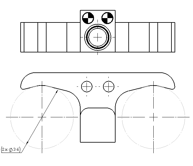
So the appropriate solution is to designate the cylinders themselves as datum targets, for example, A1 and A2. They can be shown in two adjacent views with the datum target designations appearing attached to the circular outline in one view and the straight outline in the other view. The Y14.5 standard defines datum targets only as lines, points, or areas, but an extension of a principle is possible to any shape. For example, in the digital product definition standard, ASME Y14.41 there is an example of planes tangent to a cylindrical surface used as datum targets. It is shown in thread1103-463798 in a post by pmarc. There is no reason why cylinders tangent to planar surfaces like in your case can't be designated as datum targets.