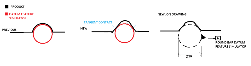
We have a product that has historically used a semicircular surface as a cylindrical datum feature to define an axis. This semicircular surface rests under gravity onto a round bar of similar diameter that acts as the Datum Feature Simulator in a checking jig.
In a new iteration of the product, we want to open the semicircular surface out to two perpendicular surfaces, which would rest on the bar in the same way, except instead of full contact, we get two tangent contacts. This is desirable as having only two tangential points of contact minimizes the chance for paint buildup, burrs, etc to exist in the contact zone, which would otherwise prevent the datum feature from making the expected contact with the datum feature simulator.
I can't find an example of how to annotate this on a drawing in y14.5. The best guess I have right now is to draw into the drawing the datum feature simulator as a dotted line, and reference it as the datum feature.
The image below shows what we were doing, what we want to do, and how I want to show it.
Is there a better/established way to show this?