Continue to Site

Eng-Tips is the largest engineering community on the Internet

Intelligent Work Forums for Engineering Professionals

  • Congratulations waross on being selected by the Eng-Tips community for having the most helpful posts in the forums last week. Way to Go!

Two Way Slab Additional Reinforcement Call-Outs 1

Status
Not open for further replies.

JNEnginr

Civil/Environmental
Aug 26, 2008
99
Hey,

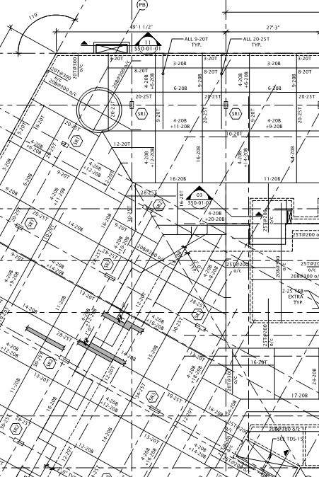
I'm trying to get people's opinions on the proper way to call out additional reinforcement required for a two-way slab.

I've seen where its just called out as (11) #7 T (11 #7 bars at the top). The instance would be additional rebar over a column.

But should the EOR show how long these bars are, and at what spacing?

If the EOR doesn't, how does the steel detailer know? Just based on embedment length? The spacing?

Thanks
 
Replies continue below

Recommended for you

Two versions that I see commonly:

OLD SCHOOL

- Use column strip / middle strip conventions in plan with typical details showing the disposition of rebar.

- Fabricator figures out the lengths of most bars using typ details.

- Good for simple, regular slabs and column layouts. Painful for complex stuff. I may post a terrible example of this later today if I have time.

- KootK wants this method to die.

MODERN METHOD

- Call out a continuous bottom mat of steel everywhere. Size and spacing.

- Add some additional bottom steel in plan where needed at specific locations. Specify length and spacing.

- Call out the column top steel either explicitly on plan (length, size, spacing) or define column "mats" elsewhere if the plan gets too busy.

- Add additional top steel where required, calling up size length and spacing.

- Cover a few simple conditions with typical details.

- This method is easier to construct, results in a zillion percent less queries, reduces shop drawing review time, and reduces field review time. It even makes for prettier drawings in most cases in my opinion.


I like to debate structural engineering theory -- a lot. If I challenge you on something, know that I'm doing so because I respect your opinion enough to either change it or adopt it.
 
To follow up, do you guys typically have a top bar plan, and a bottom bar plan?
 
Only if the system is so complex that becomes a necessity. That's part of the beauty of the continuous bottom mat approach. 90% of the bottom steel layout is communicated with a couple of plan notes smaller than my thumb.

I like to debate structural engineering theory -- a lot. If I challenge you on something, know that I'm doing so because I respect your opinion enough to either change it or adopt it.
 
And just out of curiosity, what program do you use to design the slab? I'm using RAM Concept, developing a love/hate relationship...
 
I usually have bar designations (top and bottom) on plan and in my schedule I call out the length and the placement of it. For additional top reinforcement, sometimes I call it out on plan, if it will fit, but usually I just add it to the schedule.
 
Mostly SAFE these days. A little bit of PCA slab for easy stuff. Other than licensing issues, Concept is hands down my favorite. I believe it to the be the fastest production tool for slab design by a significant margin. It's just so much easier to draw stuff than with other packages.

Below I've added the following:

1) Standard detail/plan that is often used for the middle strip / column strip detailing method.
2) An irregular plan where, in my opinion, the arrangement becomes almost incomprehensible.

Capture01_rjo8oo.png

Capture02_hriz4q.png


I like to debate structural engineering theory -- a lot. If I challenge you on something, know that I'm doing so because I respect your opinion enough to either change it or adopt it.
 
We do a bottom mat with add bars 3B5, etc. For the top mat, we call out the top bars 10T6, etc. For lengths, we reference the ACI standard detail and have the detailer do them. It is quicker in design but it takes longer during the shop phase since we have to check all the lengths and they typically need adjustment.

If I had the time and the fee, I'd call out the lengths of each bar.

We do one plan for rebar and one plan for details / geometry. Both top and bottom bars are on one plan.

When I am working on a problem, I never think about beauty but when I have finished, if the solution is not beautiful, I know it is wrong.

-R. Buckminster Fuller
 
I have absolutely no idea what's happening in KootK's drawing.
 
We often have four plans for each level in complex buildings with lots of setdowns, etc. Profile plan, bottom steel plan, top steel plan, post-tensioning.
 
Don't leave it up the scheduler to guess how you want to arrange your splices, bar shapes etc. When in doubt, draw it out!

For RC slabs, I'll draw a typical top and bottom mat and then call up additional bars where needed. I would definitely have separate top and bottom reo plans though...

 
TLHS said:
I have absolutely no idea what's happening in KootK's drawing.

For the benefit of future generations reading this thread, that is most definitely not "KootK's" drawing. It is an example of a presentation style that KootK would like erased from human kind's collective memory.

Trenno said:
I'll draw a typical top and bottom mat

How do you handle that with the top mat? A continuous top mat is a rare thing and it's an equally rare building that's regular enough to have a single column top mat be applicable.

I like to debate structural engineering theory -- a lot. If I challenge you on something, know that I'm doing so because I respect your opinion enough to either change it or adopt it.
 
Status
Not open for further replies.

Part and Inventory Search

Sponsor