Continue to Site

Eng-Tips is the largest engineering community on the Internet

Intelligent Work Forums for Engineering Professionals

  • Congratulations KootK on being selected by the Eng-Tips community for having the most helpful posts in the forums last week. Way to Go!

Trying to use GD&T on hole patterns - need advice 1

Status
Not open for further replies.

Phat Ph

Mechanical
May 15, 2018
2
Hi,

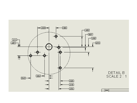
I have 8 holes that I need to define the locations of in my drawing. I feel that GD&T might be the best course of action here. As you can see in the picture, I have 4 datums, the 4th one being the "main" hole. Every other hole is referenced off of it. Is this correct? How would you do it better?

Version 1L See attached
Version 2: Using a detail view
 
Replies continue below

Recommended for you

Phat Ph - its difficult to say what exactly is the best scheme to use in your case without knowing the functional requirements however I can say that the 7x tapped #4-40 holes are free to rotate around the .280 hole marked datum D (no datum constraining rotation with only A|D in the FCF and datum D is only applied to 1x .280 hole in the upper left vs. a pattern of holes). Additionally it looks like all your size dimensions/tolerances and position tolerances only apply to the pattern of holes in the detail view as there are no notes on the snapshot you have provided showing how this applies to the rest of the holes.

Just by looking how you have it set up it looks like you may be trying to accomplish something similar to fig. 7-37 in the Y14.5 standard, however whether you want to do a multiple single segment callout on the second series of holes or just have a single FCF including your datum D is up to you - just make sure you that however you set up your FCF/DRF that you constrain rotation somehow. The "INDIVIDUALLY" callout is of course not a requirement however it allows control of each pattern in the series (in your case each set of 7x #4-40 and 1x .280 holes) by itself instead treating every hole of the same size in the part as a single pattern, which can be beneficial if there is no need to treat them all as a single pattern.
 
 https://files.engineering.com/getfile.aspx?folder=08d34399-868a-4321-98c9-42f29111887d&file=fig_7-37.JPG
Agree with chez311.
Didn't have my book handy, but this is exactly the illustration that immediately came to mind. Good work!

"For every expert there is an equal and opposite expert"
Arthur C. Clarke Profiles of the future

 
CH - Thanks! It was on the top of my mind because it was referenced in another thread but I think thats exactly the direction OP probably wants to go in.

Phat Ph - I just noticed that you have two versions, the only significant difference between which as far as I can tell is the way the basic dimensions are applied. This does not really matter, except for the fact that in your version two you have crossed out any dimensions referenced back to datums B and C - you need to provide at least one dimension back to each datum feature so that the rest of the dimensions are still connected in some way back to those datum features.
 
Chez, is including this extra line (see red arrow in attached) enough to constrain rotation? Was that the only thing incorrect or is there also more errors in my method of defining the positions of each 4-40 hole?

The function of this piece is as follows: there are a variety of "boards" that will insert into the .280 diameter hole. Then, each board has its individual bolt pattern that will bolt up to two or three of the 4-40 holes.
I wanted to finish defining the tolerances and positions of the first set of holes. My plan for the rest of the set would be to note that it will be patterned and dimension the distance between each pattern.
 
 https://files.engineering.com/getfile.aspx?folder=2d774174-38df-4a13-91f7-3e897a55b4e3&file=New_Cap.PNG
Phat Ph - yes that should be sufficient, though I see for whatever reason you have removed all datum references - these should definitely be included, I assume it just has to do with however you took the snapshot.

Also a better drafting expert than I could attest and say whether this is allowable but if you are planning on noting that it will be patterned and putting a single dimension in each direction between patterns then I would probably go with leaving the basic dimensions in the detail view between the 7x holes to show exactly which dimensions will be patterned per your below. The pattern and "INDIVIDUALLY" notation on the 7-37 is probably almost exactly what you want to emulate from what you have described.

detail_dims_gqjmfo.png
 
Status
Not open for further replies.

Part and Inventory Search

Sponsor