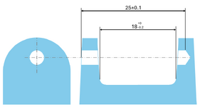
3DDave, thats a lot of questions, I'll try to clarify:
What does the mating pin/rivet do?
Primarily it allows the mating part (of dim 18) to swivel.
If the mating part has a flange, why isn't there a spotface to properly stop it?
This rivet has a knurled surface at one end for interference fit to the left side hole. Once inserted, it just has to be approximately flush with the left side surface. The "stopper" is from the interference fit and the tapered end.
If there isn't a flange, what difference does the left-hand face make to the depth when you are trying to maintain a wall thickness on the right?
Since the tapered end is also a "stopper", the depth is controlled to ensure the wall thickness on right side is strong enough.
What spaces the captured part to not move right and left to interfere with the tapered/drafted surfaces?
Nothing. Although the part moving in dim 18 has clearance to the draft surfaces, it is allowed to shift left/right (with grease) and basically contact the draft surfaces during movement. There are no functional issues with this.
What do you expect a CMM to measure in terms of where you would have the points taken?
If I create Profile of surface spec's for the pictured part's outer & inner surfaces, I would probe several points on every relevant surface.
Are those locations different than are being measured now?
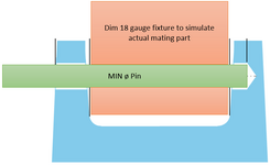
Yes. Actually nothing is being "measured" now. To check dim 18: the current method uses gauge fixtures & pins to simulate the maximum size of dim 18 mating part. This gives a AC/NC result.
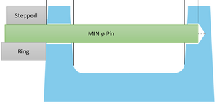
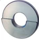
To check depth of pin, a MIN ø pin (longer than dim 25 is inserted and it will protrude from left side hole. This protrusion is judged by a stepped ring fitted onto it, which gives a AC/NC result.
What is the exact setup and measuring sequence currently and where does the stack-up error come from?
Setup & measure sequence as above.
Stack up error for dim 18: the gauge mating part is close fit to the MIN ø pin (error from close fit & from looseness of MIN ø pin); So the mating part is slightly overcompensated for these "errors", and this adds to the errors. (its an indirect checking method based on actual function). I'm wondering is this method common for other industries?
For dim 25: comes from looseness of MIN ø pin.
There are 2 main reasons we want to change the current method:
1. To get data to plot stability of process
2. To have data for troubleshooting purposes
The question of whether these reasons are worth the change was discussed and the consensus was to try first.
Any feedback or comments are welcome.


