Continue to Site

Eng-Tips is the largest engineering community on the Internet

Intelligent Work Forums for Engineering Professionals

  • Congratulations cowski on being selected by the Eng-Tips community for having the most helpful posts in the forums last week. Way to Go!

True Profile Definition

Status
Not open for further replies.

pmarc

Mechanical
Sep 2, 2008
3,227
Hello,

Below is a snapshot taken from the most recent Tec-Ease tip available on their website. My question would be following: Does anyone think that the true profile between points S and T (clockwise) has not been fully defined? I am specifically thinking about close vicinity of points S and T. Thank you!

capture_bjnd61.jpg
 
Replies continue below

Recommended for you

CH -- I still don't see how you can think that the 65 +/- 0.25 on pmarc's sketch could be legal. Everything you've written in your latest post is correct, but it doesn't address the issue.

To better address the issue, let's take the four pictures you just posted, and add the all-around symbol to the profile controls. Do you think that ANY of the four pictures could then have a plus/minus tolerance on the 20? According to Y14.5, the answer should be no.

John-Paul Belanger
Certified Sr. GD&T Professional
Geometric Learning Systems
 
To add to what you said Belanger, since the last figure (form and size) the same point would be made not with an all-around symbol but by instead switching the basic 20 diameter callout to a plus/minus tolerance since its representing a cylinder.

But yes, I fully agree with your point. The answer according to the way I'm interpreting Y14.5 should definitely be no in all four cases.
 
CH said:
I really don't want to enter lengthy discussion here.
Oh no, you do want to enter lengthy discussion :). Otherwise you would stop here instead of quoting the standard further.

What would you say about following interpretation of the quotes?:
"Profile tolerances are used to define a tolerance zone to control form or combinations of size, form, orientation, and location of a feature(s) relative to a true profile"
This basically means that there has to be a true profile to be able to use a profile tolerance relative to it.

"A true profile is a profile defined by basic radii, basic angular dimensions, basic coordinate dimensions, basic size dimensions, etc. etc."
This basically means that to talk about true profile the profile must be defined with basic dimensions. Notice that no other type of dimensions has been mentioned here.

So if the contour of the hole in my example is not fully defined with basic dimensions all around (i.e. it does not really satisfy the true profile definition for the entire feature), is it legal to apply all around profile tolerance to it?

I am not really expecting you to answer that question. I merely want to show that the quotes you offered can be interpreted differently to support different point of view.

------

And to your most recent illustration with four different cases, I do not think there is a need to debate about the 3rd and 4th case. These are classic examples of profile application - every dimension is basic = no controversy.

As for case #1, the profile tolerance is acceptable because the true profile of the upper face can be understood as perfect plane that does not require any basic dimension (this has been mentioned on this forum many times before). Why someone would not use flatness instead of profile to avoid any confusion is another story.

As for case #2, the profile tolerance is acceptable because the true profile of the upper face can be understood as perfect plane that does not require any basic dimension. Why someone would not use parallelism instead of profile to avoid any confusion is another story.
 
Belanger,

Are you saying that the true profile of the conical surface is fully defined with basic dimension(s) in Fig. 8-17, but not in Fig. 8-18?


pylfrm
 
CH and pmarc,
I think you guys have a violent agreement. Don’t you?
Or you fine gentlemen are debating the “legality” of the callout. Not sure even the standard is crystal clear about this legality.
Why I am saying this? Because if it would (be clear about the legality) Tec-Ease wouldn’t make that mistake in the first place. It is like putting M or L modifiers on the profile callout (you wouldn’t do it, correct?). So, it is a gray area and some people are more conservative than others.

Pmarc,
pmarc said:
“…… and imagine that the the directly toleranced dimension has been converted to basic. This will change the requirement for the upper face entirely - instead of controlling single line elements only for their form and orientation to the specified datums, the callout will additionally control location.”

I don't even want to think that way.
I want to think that the power to change the callout orientation versus location is given by the GDT callout and not by the ± direct toleranced versus basic dimensions. Basic dimension locate or orient the tolerance zone and that’s it. Then the tolerance zone limits the imperfection of a feature's location and/or orientation. The presence or absence of a basic dimension cannot have any effect regarding what profile controls.

That is my line of thinking that I am embracing (which, by the way, I got from reading different discussions here on this forum over the years). ---some of those discussions referenced in my earlier post in this thread---

And I understand that might not be the agreed concept, but I think it is the one aligned with the MBD future development….hopefully.

Hopefully you understand what I mean.
 
pylfrm -- The cone in Fig. 8-17 can't really be pinned down with a basic diameter because a cone is constantly changing diameter as you move lengthwise. Since there's no datum taken from the end face, there's no way to lock down where that frozen, basic diameter would be. So the profile tolerance zone becomes a best-fit zone.

In Fig. 8-18, however, they referenced the end face as a datum (well, datum feature). So they should have made the diameter basic because there's a definite reference plane in the lengthwise direction.

FYI -- in the draft version of the upcoming revision to Y14.5, I think this problem is solved with the "dynamic profile" modifier.

John-Paul Belanger
Certified Sr. GD&T Professional
Geometric Learning Systems
 
Well, Well. ..Interesting debate and how multiple legal interpreations COULD be made about (and when) ± direct toleranced dimensions are intermingled with GD&T callouts.
Probably it is "legal" to do it, but refrain from doing it.
8-27, 8-18 figures have been discussed many..... many times here (and elsewhere) before, with no acceptable (read standardized) agreement.
Some of the experts even suggested to have those figures "adjusted" or even removed from the standard.


greenimi said:
Probably it is "legal" to do it, but refrain from doing it.
8-27, 8-18 figures have been discussed many..... many times here (and elsewhere) before, with no acceptable (read standardized) agreement.

I won't get into whether I think those figures are legal, especially 8-18 since thats such a hot button topic, but see my original post about what I thought the reasoning behind them was and why I think those figures (8-17/8-18/8-27) all fall into the "legal grey area but bad/confusing practice which should probably be avoided" which is at least consistent in its treatment of the true profile (although debated about actual interpretation) vs. CH's take on the 2nd example provided by pmarc (has 65 +/-0.25 mixed with a 0.25 all around profile tolerance) which I think is pretty clearly not allowed by the standard and its definition of true profile.

Belanger's response about whether +/- tolerance on any of those figures would be allowed with the all-around symbol added drives my point home. I don't think any of those would result in an allowable definition of the true profile by mixing in toleranced dimensions.
 
Belanger,

Let me ask another way:

For ASME Y14.5-2009 Fig. 8-17, do you think the true profile of the conical surface is fully defined with basic dimension(s)?

For ASME Y14.5-2009 Fig. 8-18, do you think the true profile of the conical surface is fully defined with basic dimension(s)?

Shouldn't both of these questions be answerable without any consideration of profile tolerances or datum features?


pylfrm
 
image_omoi8f.jpg


May I ask one additional question, please:
If in the embeded picture datum feature A is added in the profile callout for the HEX, what would be the additional characteristic ( if any) ( orientation somehow?) that the adjusted profile will control? Again, I am interested in the adjusted profile of the HEX (the one used in combo with the position with Boundary)

Will create any additional value if datum feature A is to be added and if yes what that value would be?

Also will create any conflict with the positional callout?

Thank you for your input.
 
Hi All,

Interesting discussion of what happens when directly toleranced dimensions are mixed in with profile tolerancing. A confusing mess.

greenimi,

Regarding the effect of a datum feature A reference on the hex, this is reasonably straightforward (I think). I would say that this would refine the orientation of the hex. Specifically, the zones for the hex surfaces would be oriented to datum A - this would limit how tilted any of the 6 surfaces could be (within 0.1). This would not conflict with the positional callout.

Evan Janeshewski

Axymetrix Quality Engineering Inc.
 
axym said:
Regarding the effect of a datum feature A reference on the hex, this is reasonably straightforward (I think). I would say that this would refine the orientation of the hex. Specifically, the zones for the hex surfaces would be oriented to datum A - this would limit how tilted any of the 6 surfaces could be (within 0.1). This would not conflict with the positional callout.

Evan,
Thank you very much for your replay. So, if the same datum feature A is added in the profile callout in fig 8-24 (Y14.5-2009) then this would NOT refine the orientation of the shape, correct? That is because profile tolerance in the 2009 standard picture (8-24) is bigger than the position. Will coarsen it? Is that even possible?

Is my understanding correct?

Thank you again

 
Seems like some side topics have evolved from the main discussion. Feel free to continue. Just wanted to go back for a moment to the main subject and show what ISO has to say about compound contours not fully defined with basic dimensions yet controlled with profile tolerances.

So below is a snapshot from the latest version of ISO 1660 standard "Profile tolerancing" issued in 2017.
capture_4_nwois8.jpg


Another shapshot showing what Rule A in that document is:
capture_5_y4mxme.jpg


The interesting part of it is the last sentence - they allow application of profile tolerances to features of size controlled with directly toleranced dimensions, as shown below, but then the profile tolerance value always needs to followed by OZ (offset zone) modifier:
capture_6_fi5hu4.jpg


Sometimes I wish Y14.5 contained some examples of bad dimensioning and tolerancing practices that should be avoided to avoid ambiguity. That would sometimes make life much easier.
 
greenimi,

These are interesting questions, that lead to some bizarre conclusions.

I would say that in general, additional geometric tolerances or datum feature references never coarsen the requirements. The only exception to this is derived median line straightness (or derived median plane flatness).

Adding a reference to datum feature A in the profile callout in 8-24 would refine the orientation of the shape, despite the fact that the profile tolerance value is larger than the position value that also references datum feature A.


Evan Janeshewski

Axymetrix Quality Engineering Inc.
 
pylfrm said:
Shouldn't both of these questions be answerable without any consideration of profile tolerances or datum features?
When I first saw Figures 8-17 and 8-18, I thought that both of them violated the requirement for defining a true profile. Upon further thinking (and with comments from an old post by user DeanD3W) I softened my opinion about Fig. 8-17.

So I've picked my battle to argue that Fig. 8-18 is not per the standard's definite rules. But my thinking on 8-17 was that profile doesn't control size of the cone because the tapered tolerance zone is on a "sliding scale" in the left/right direction. Thus, the toleranced dim on the diameter doesn't bother me as much.

John-Paul Belanger
Certified Sr. GD&T Professional
Geometric Learning Systems
 
Evan,
Interesting statement about bizarre conclusions.

Okay, here is my follow-up questions:

Your quote from this thread:
axym said:
”Adding a reference to datum feature A in the profile callout in 8-24 would refine the orientation of the shape, despite the fact that the profile tolerance value is larger than the position value that also references datum feature A.”

A few years ago when we talked about the position refinement in this thread:
you said:
axym said:
John-Paul,

Here's one for you. Let's say that I want to refine the orientation of the closed shape in Fig. 8-24 of '09. I can't use an Orientation tolerance because the feature isn't a planar surface or a regular feature of size. One way to do it (and possibly the only way) would be to add a lower segment to the Position tolerance and change it to a composite FCF. The lower segment could be POS|dia 0.2(M)|A|B| or something like that. The lower segment of the composite Position FCF would act purely as an orientation tolerance, refining the orientation of the feature without controlling its location.

A Position tolerance controlling orientation only. What do you think?
Evan Janeshewski

And my questions are: do you see a conflict between these two quotes? Are we not talking about the same physical feature/physical shape? I am not saying there is one (conflict), but I am wondering what changed in your thinking over the years (because for sure the standard Y14.5, didn’t). I am trying to follow your thoughts.

So, can you refine the orientation of the shape in two different ways?
Either adding datum feature A on the profile (as per this thread) or “upgrading” the entire position to a composite one (as per the thread from a few years back)? Also you said “probably the only way”……

Something changed in your knowledge about this language over those years and I am trying to educate myself what was that. Again, I am not putting you on the spot and I am not holding your feet to the fire !! Do not think I am looking for conflictual statements. I am trying to clearly understand this GDT language (if that's ever possible). Thank you for your patience with me (undereducated member of this forum)

Pmarc,

Sorry, I am entirely guilty for one of the side topics. I appologise for that. I perceived some tension-animosity between some participants on this discussion /members of this forum and I said that instead of leaving this thread to die is better to hijack it for my own edification and with my own set of questions.

Thank you for providing ISO stuff. I always wanted, and still do, to improve my education in ISO. And I agree with you (with my limited exposure to ISO) that some GPS standards have pictures of what means ambiguity in dimensioning and also what means unambiguous scheme. (ambiguous versus unambiguous side by side). I like that too.

And by the way: “Happy Father’s Day” to all of you!
 
greenimi,

I read through the old thread from 2012 that you referenced - it's interesting to see what we were thinking back then. I think that what I said about the "composite boundary position" tolerance was correct (or at least I still agree with what I said). You're correct that refining the orientation using the profile tolerance isn't something that I had thought of before until you proposed it in this thread. So I would agree that the orientation of the shape could be refined in at least two different ways (using a composite position tolerance or a profile tolerance). Exactly how the orientation would be refined would be quite different in each case, however. We can't just compare the tolerance values in the FCF's to see which tolerance would refine the orientation the most - it's not that simple.

Don't worry about putting me on the spot or looking for conflicting statements (actually, I like your term "conflictual") ;^). This is a good thing! As you know, I regularly question the logic and consistency of statements in Y14.5 and by other members of this forum, and I expect the same in return. I can honestly say that I have gained a lot of new insights from having my feet held to the fire by pmarc, J-P, CH, pylfrm, 3DDave, powerhound, yourself, and others over the years.

Evan Janeshewski

Axymetrix Quality Engineering Inc.
 
Evan,
I still believe that a separate orientation callout (perpendicularity) could be used to refine orientation of the hole in fig. 8-24. So this would be another method to refine orientation. I am purposefully not calling it the third method, because at the same time I believe that the composite position shall not be a choice (as long as there is only one feature considered).

Para. 6.4.2, that you referred to in that 2012 discussion, talks purely about orientation tolerance zones when axis/center plane interpretation is used. With boundary interpretation employed (which is actually the only interpretation method that can be used in case of features like in fig. 8-24), the virtual condition boundary shape would be identical with the shape of the toleranced feature, and conceptually I see nothing wrong with that.

With that said, I agree with you about different possible ways to refine orientation of the shaped hole. I am not sure if the intent of the committee was to allow for usage of datum references in the profile callout, but it would be hard to argue that this is illegal.

And to greenimi's question/concern about dependency of the tolerance values for profile and position in fig. 8-24 (and in general), I would say that any combination of the two tolerance values is acceptable as long as it does not lead to zero or negative size of the smallest of the characteristics that constitute the irregular virtual condition boundary for position tolerance. So in the fig. 8-24, if we assume that profile tolerance value is 1.2, the position tolerance value can be as much as 4.8 - for this combination of tolerances the value of the left upper corner radius of the virtual condition boundary will be zero.
 
pmarc said:
I am not sure if the intent of the committee was to allow for usage of datum references in the profile callout, but it would be hard to argue that this is illegal.

I've seen some GD&T training material available from Mark F. (AGI-Advanced) and a primary datum feature is shown in the profile callout. I also understand and agree that might be a personal opinion of the author and he is *IN* the commitee and not *THE* commitee.

pmarc said:
I am purposefully not calling it the third method, because at the same time I believe that the composite position shall not be a choice (as long as there is only one feature considered).

About the legality of the composite position when only one feature is considered, the same author stated somewhere on linkedin AGI Group:

"In re-reading through the Composite Position section of the 2009 standard, it is clear to me that the *intent* of the definition is for it to apply to patterns of features of size, thus it is clear to me that the *intent* is for it to apply to more than one feature of size at a time. However, if I put my lawyer hat on (as much as that hurts to do), the Composite Definition, or any other definitions in the standard to my knowledge, never clearly define what constitutes a "pattern." There is a lot of implication, but no definitive definition. So, one could argue that I could have a "pattern of one" feature of size. And, of course, we see people do that exact thing all of the time out there in actual industry. The same interpretation (i.e. orientation only) would be the way we would interpret a single feature of size with a Position feature control frame back to a primary planar datum feature only when only an orientation relationship exists between the planar datum feature and the feature of size in question, such as when we are going to use that feature of size as our secondary datum feature. i.e. The Position callout in that case would really only be serving as an orientation control.

So, traditionally, we have simply interpreted the lower tier(s) of a composite postion feature control frame applied to a single feature of size to be an orientation refinement for that single feature of size. And, as such, one could instead use a single-segment position for that feature of size, then follow it up with whatever orientation refinements we might need using separate orientation feature control frame callouts. And in the case of the secondary datum feature of size with a Position feature control frame (rather than just an orientation control), we would normally advise simply using an orientation feature control frame instead. "


Q_-_Copy_dnxt3u.jpg


Pmarc, Evan, 3DDave, greenimi and everbody

Speaking about extension of principles, committee, and the intent (legality) of the callouts within the standard

Could you please let me know what do you think about the following datum scheme:

Is, in your opinion, the intent of the standard to allow this?

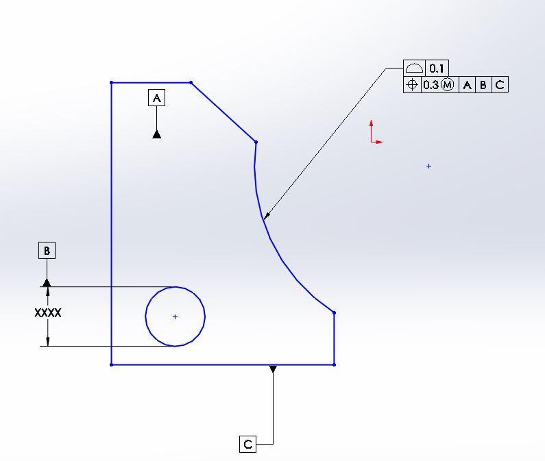
Datum feature A: flat back surface, controlled with flatness
Datum feature B: hole, defined for size with ± and controlled with perpendicularity to A
Datum feature C: lower surface, defined with profile to A primary and B secondary.
Part defined with basic dimensions: basic distance from datum feature C to the hole in the center, basic radius for the feature controlled with profile and position combo, basic angles, basic length, basic width.

Question:
Is the feature shown with profile + position “combo” correctly defined per ASME Y14.5-2009?

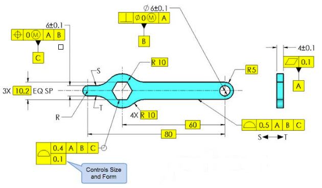
Supplier QE states: “combo” depicted above is reserved for closed shapes as shown in Fig. 8-24.


Designer stands behind his GD&T callout: his stance is that nowhere on 8.8 (Combined Controls) is specified that the shape of a noncylindrical feature should be closed and surface interpretation prevails anyway. Advantage: using MMC on the profile.

Note: Part assembled with clearance between the questioned surface and its mating component. .


One of my coworkers posted the same question on different site, but he did not get any answers, so I said, let me try on eng-tips.


What do you think? Has this scheme envisioned by the standard?
 
Status
Not open for further replies.

Part and Inventory Search

Sponsor