greenimi,
Let me try:
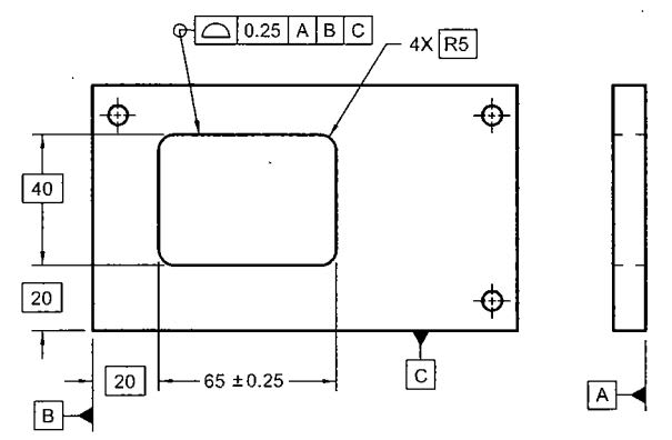
Q1: In the original version of the tip the 6 width and the R dimension at the left end of the part should have been basic to make the all-around profile meaningful and correct. If that had been done, the basic distance between the discussed arc centers would not have been required as the distance between the arcs in vertical direction would have been controlled by the tangency between the arcs and the sides of the 6 width.
Q2: You should ask Tec-Ease. It is not that the dimension for width C has to be basic. There is nothing wrong in keeping it directly toleranced. But if that is done, the relationship between discussed arcs is no longer basic and that is why the extra basic dimension is needed.
Q3: I think that in general the "beauty" of basic dimensions is that one does not have to worry about overdimensioning too much. Of course, this does not mean that applying too many basic dimensions is recommended practice. I have seen situations where downstream drawing users were seriously confused by that.
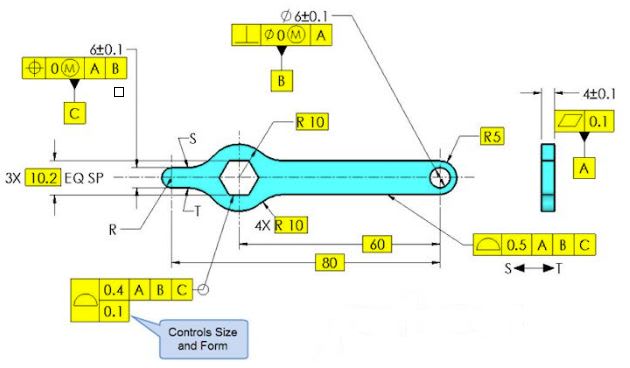
If you ask for a situation where addition of basic dimensions could cause unintended consequences, just think about fig. 8-27, mentioned by you, and imagine that the the directly toleranced dimension has been converted to basic. This will change the requirement for the upper face entirely - instead of controlling single line elements only for their form and orientation to the specified datums, the callout will additionally control location. The effect of that will equal to profile of a surface requirement.
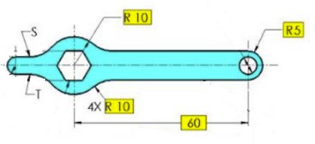
Q4: The argument could be made, in my opinion. Imagine that this drawing is converted to Model Based Definition (MBD). In MBD there is no requirement to show basic dimensions (they are taken directly from 3D model), but also there is no requirement that they can't be shown. If basics are shown, someone can still argue that the characteristics that have not been shown should be taken from 3D model. And in fact this is how any CMM inspection software will read the profile requirement between points S and T. It will simply ignore the issue I have raised; it will treat the entire profile between points S and T as fully defined.
This is also one of the reasons why the approach shown in fig. 8-18 mentioned by J-P is vague. In MBD any CMM software that would be able to read the profile callout directly from the model would create 0.02 wide profile tolerance zone that would not only be fixed in orientation and location to the speficied datums, but also fixed in size (i.e. the CMM would treat the diameter 24 as basic). In order to avoid this, the CMM software must be somehow programatically told to ignore the size contraint, and this is where the dynamic profile tolerance zone modifier comes into play (yes, I remember we already talked about its questionable usefulness in case of a cone).
![[lol]](/data/assets/smilies/lol.gif "[lol] [lol]")