Hi
Refer attachment.
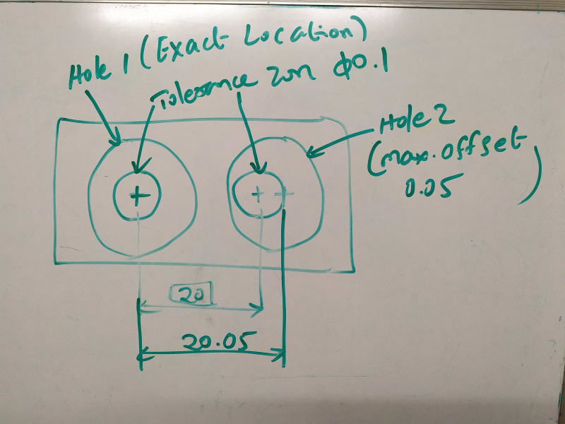
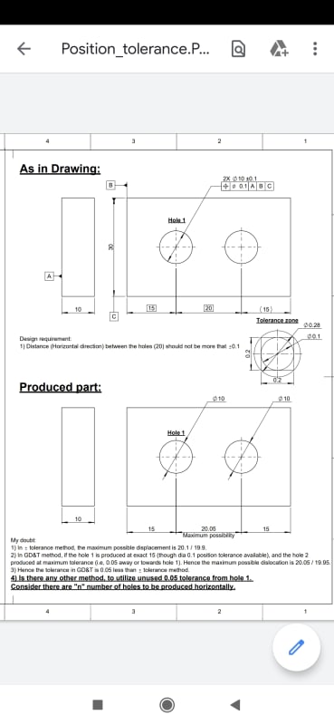
My doubt:
1) In +/- tolerance method, the maximum possible displacement is 20.1 / 19.9.
2) In GD&T method, if the hole 1 is produced at exact 15 (though dia 0.1 position tolerance available), and the hole 2
produced at maximum tolerance (i.e, 0.05 away or towards hole 1). Hence the maximum possible dislocation is 20.05 / 19.95.
3) Hence the tolerance in GD&T is 0.05 less than +/- tolerance method.
4) Is there any other method, to utilize unused 0.05 tolerance from hole 1.
Consider there are "n" number of holes to be produced horizontally.
Refer attachment.
My doubt:
1) In +/- tolerance method, the maximum possible displacement is 20.1 / 19.9.
2) In GD&T method, if the hole 1 is produced at exact 15 (though dia 0.1 position tolerance available), and the hole 2
produced at maximum tolerance (i.e, 0.05 away or towards hole 1). Hence the maximum possible dislocation is 20.05 / 19.95.
3) Hence the tolerance in GD&T is 0.05 less than +/- tolerance method.
4) Is there any other method, to utilize unused 0.05 tolerance from hole 1.
Consider there are "n" number of holes to be produced horizontally.