Continue to Site

Eng-Tips is the largest engineering community on the Internet

Intelligent Work Forums for Engineering Professionals

  • Congratulations waross on being selected by the Eng-Tips community for having the most helpful posts in the forums last week. Way to Go!

+/- Tolerance vs GD&T 1

Status
Not open for further replies.

Sa-Ro

Mechanical
Jul 15, 2019
279
Hi

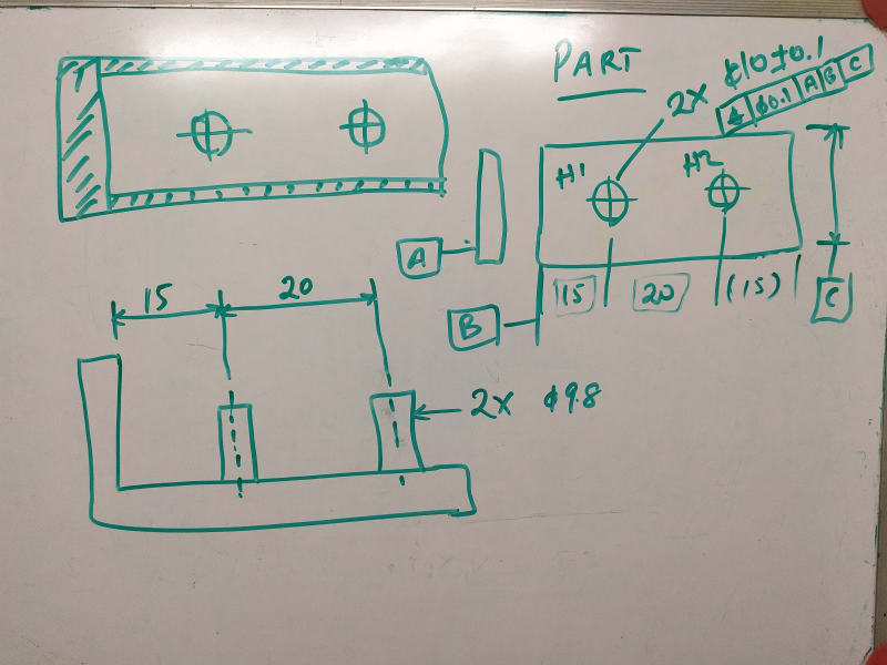
Refer attachment.

My doubt:
1) In +/- tolerance method, the maximum possible displacement is 20.1 / 19.9.

2) In GD&T method, if the hole 1 is produced at exact 15 (though dia 0.1 position tolerance available), and the hole 2
produced at maximum tolerance (i.e, 0.05 away or towards hole 1). Hence the maximum possible dislocation is 20.05 / 19.95.

3) Hence the tolerance in GD&T is 0.05 less than +/- tolerance method.

4) Is there any other method, to utilize unused 0.05 tolerance from hole 1.
Consider there are "n" number of holes to be produced horizontally.
 
 https://files.engineering.com/getfile.aspx?folder=cc04e60f-ae7c-481a-a0d1-4de608559bea&file=Position_tolerance.PDF
Replies continue below

Recommended for you

Sa-Ro said:
Hole 1 and 2 is located from datums.

In my last post I have shown only tolerance zone.

Didn't we already agree that these datums are not functional?

Sa-Ro 13 Jun 20 16:46 said:
You are right. Datum B and C are not locating the part.

Let's forget the datums. Consider two holes only

Did you forget about it or did you change your mind?
 
Ok. Like datum shift, the hole 1 can be shifted to max possibility to accept 20.1.

Since the horizontal and vertical distance should not move more than 0.1 between holes, I have not opted for diagonal distance of 0.2 square, which will allow 0.28 total tolerance.
 
I have not changed my mind.

Datum B and C are not locating.

But, if 15 dimension from hole is increased, the adjacent component may interfere.
 
Ok, give me some time to understand and revert.
 
IMG_20200614_021301_eqyxsz.jpg


Hole 1 is produced at dia 9.9 and located at 15

Now the hole 2 is produced at dia 9.9, located at 20.05, max possibility from dia 0.1 position tolerance.
 
Sa-Ro said:
Datum B and C are not locating.

This is not correct. In your latest figure, as well as your OP, datum B and C absolutely provide location constraint for your position tolerance zone.
 
I thought the pins are locating.

Ok. In this case 20.1 is possible by by shifting hole 2 only?
 
Sa-Ro said:
But, if 15 dimension from hole is increased, the adjacent component may interfere.

Sounds like you should apply a profile tolerance to the sides referenced from the holes (holes specified as a datum feature) not the other way around.
 
Sa-Ro said:
I thought the pins are locating.

The sketch of your gage doesn't agree with that.
Either datum features B and C are specified they way you did or the pins locate. It can't be both. To decide what are the locating features you have to consider what features constrain translational degrees of freedom in your pneumatic assembly and therefore also in your gage.
Datum feature A the primary constrains one translation but it mainly orients your part by constraining two rotation DOF. Now, which features constrain the additional two translations in your pneumatic assembly?
 
Then you should follow what chez311 suggested in his last post. Axes separation of 19.9-20.1 will be allowed by position on the pins with reference to A only so there should be no concerns about any unused tolerances.
 
You're welcome.
Just make sure that the inner boundary of the holes resulting from the size tolerance and the 0.1 position tolerance does not violate the outer boundary of the pins in the mating part. drawoh's last post in this thread describes this thoroughly. This is the important thing you should focus on.
 
Status
Not open for further replies.

Part and Inventory Search

Sponsor