Continue to Site

Eng-Tips is the largest engineering community on the Internet

Intelligent Work Forums for Engineering Professionals

  • Congratulations waross on being selected by the Eng-Tips community for having the most helpful posts in the forums last week. Way to Go!

+/- Tolerance vs GD&T 1

Status
Not open for further replies.

Sa-Ro

Mechanical
Jul 15, 2019
279
Hi

Refer attachment.

My doubt:
1) In +/- tolerance method, the maximum possible displacement is 20.1 / 19.9.

2) In GD&T method, if the hole 1 is produced at exact 15 (though dia 0.1 position tolerance available), and the hole 2
produced at maximum tolerance (i.e, 0.05 away or towards hole 1). Hence the maximum possible dislocation is 20.05 / 19.95.

3) Hence the tolerance in GD&T is 0.05 less than +/- tolerance method.

4) Is there any other method, to utilize unused 0.05 tolerance from hole 1.
Consider there are "n" number of holes to be produced horizontally.
 
 https://files.engineering.com/getfile.aspx?folder=cc04e60f-ae7c-481a-a0d1-4de608559bea&file=Position_tolerance.PDF
Replies continue below

Recommended for you

Hi Sa-Ro,
Your drawing shows a 0.28 circumscribed circle that contains your 0.2X0.2 square tolerance zone resulting from the direct tolerancing method (+/-0.1). In the general case, if the +/-0.1 tolerance is what's needed to make the part functional, a 0.28 diameter size position tolerance will also ensure the same function, so if you put the 0.28 value in your position FCF instead of 0.1, you can enlarge your tolerance and maintain the same functionality (note that the 0.28 diameter circle is larger in area than the 0.2X0.2 square).
 
You can use (ASME Y14.5-2009 Fig. 7-28) Bidirectional Positional Tolerancing, Rectangular Coordinate Method

57% extra tolerance versus 21.5% less see below

Copy-paste different discussion

"The argument is that if the deviation at the corners of the tolerance zone (diagonal direction) is functionally acceptable, then that same deviation should be functionally acceptable in the orthogonal directions. This is usually true when it's a round feature that mates with another round feature. So it makes sense to circumscribe the cylindrical zone outside the square.

If the designer based the +/- limits on allowable deviation in the orthogonal directions, then it is possible that the square zone is too forgiving - the deviation at the corners might be unacceptable. In this case, it would make sense to use a cylindrical zone that is inscribed inside the square (which would have 21.5% less area). For some reason, GD&T consultants don't focus on this ;^).

Evan Janeshewski

Axymetrix Quality Engineering Inc.
"
 
Sa-Ro,

By fixing the left hole at 15 you're creating what I think is a false comparison. One of the major differences/issues (among many others) with directly +/- toleranced position is the way the locations stack. For the +/- case the two holes can be at a maximum separation of 20.1 no matter where the left hole comes in at. For the position tolerance each hole must be produced on the extreme of each tolerance zone to get the maximum 20.1 separation.

This is typically a good thing! Take it in terms of your datum feature B (only denoted in the right "GD&T" case but lets assume this is an important feature for both cases) - if you have n holes each dimensioned 20+/- 0.1 from each other, then your maximum distance from datum feature B for the directly toleranced case would be 15.1+20.1*n and for your standard position tolerance with basic dimensions is 15+20*n+0.1 which means that your nth hole location isn't dependent on the rest and you don't run into issues with tolerance accumulation.

In the schemes you have shown this means that for n=10 holes your directly toleranced case has the potential to allow a hole at 15.1+20.1*10=216.1mm away from datum feature B and the standard position tolerance allows a hole at 15+20*10+0.1=215.1mm away from datum feature B. Eliminating tolerance stacks like these is one of the advantages of a position tolerance.

If you are dead set on using directly toleranced dimensions for location it may be wise to dimension only from the critical feature - however this of course doesn't take into account issues with how these directly toleranced dimensions are verified (no repeatable datum feature references to start). In that case if everything was dimensioned from B (first hole 15+/-0.1 and second hole 35+/-0.1) then a better comparison would be a 0.2 position tolerance not a 0.1 position tolerance (the total width of a +/-0.1 tolerance band is 0.2 not 0.1).
 
+/- IS GD&T. What you are comparing to is FCFs vs no FCFs.

"GD&T" is a marketing term that includes +/- tolerancing.
 
@ Burunduk

Kindly consider the design requirement.

"Distance (Horizontal direction) between the holes (20) should not be more that 0.1"

If we use dia 0.28 position tolerance, both the holes can move to maximum possibility and locating at 20.28 which is violating design requirement.

That is why I used dia 0.1 - to ensure the max location is 20.1.

@ Greenimi

I accept your point and opted for 21.5% less tolerance zone. Since the design requirement is 20.1 / 19.9.

Rectangular tolerance zone may be used as 0.1 (Horizontal) X 0.3 (Vertical) - which will give 20.1 / 19.9.

@ Chez311
I accept, cumulative tolerance is more in +/- tolerance - for 10 holes, 216.1.

Position tolerance will maintain dia 0.1 tolerance for all holes wrt datum B and between nearest hole.

@ 3DDave

Yes. your are right.

Now, I will explain my requirement little bit more clearly.

Only the distance between the hole in horizontal direction is concerned.

Max possible distance between hole is 20.1 / 19.9.

It is possible without FCF method.

With FCF, to ensure 20.1 / 19.9, maximum allowable displacement of two holes are dia 0.1 each.

In this case, if hole 1 is produced at exact location, as per my requirement, the second hole can dislocate to 20.1 / 19.9.

But due to position tolerance of dia 0.1, the hole can dislocate 0.05 either side. which will give 20.05 / 19.95.

Hence there is unused tolerance of 0.05 from hole 1.

How to use that?
 
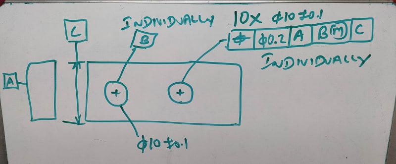
Sure. Use one hole as a datum feature and reference it MMB in an FCF on the next hole. Then you can add "INDIVIDUALLY" for both callouts to repeat N times. You might have to create a detail view so the users of the drawing won't call for clarification more than a few times.

Of course this will let the tolerance accumulate across the part in a spectacular way.
 
If you truly only care about the hole to hole spacing be allowed to be anywhere between 20.1 and 19.9 for every hole simultaneously there isn't really a standard way to do this*. This is typically an undesirable trait as it allows your furthest holes to be between 20.1*n and 19.9*n away. Not only that, but the resulting variation of each successive hole also affects the tolerance zone of the next hole. Unless you are hand drilling these with a fixture (ie: have a pin and drill bushing that only fixtures to the hole next to it or something strange) or fixturing it many multiple times manufacturing won't really be able to take advantage of the added tolerance/stack this results in. If these are instead made on a CNC mill and all the holes are inside the envelope of the machine and can be made in one setup the resulting tolerances from manufacturing will not stack like that.

*Except with creative use of the INDIVIDUALLY notation, I was going to add this but 3DDave beat me to it.
 
@ 3DDave

1_chg2yw.jpg


Am I right?

@ Chez311

It is planned to machine in a VMC.
 
It is planned to machine in a VMC.

If thats the case, and especially if its done in a single setup, expect the hole locations to have variation centered around nominal or ALL offset together in one direction by the same amount (affected by fixturing). You will not get variation which will continue to increase or be affected by each successive hole as you go from hole to hole to hole down the line like the +/- tolerancing or INDIVIDUALLY would allow.
 
I did suggest putting that in a detail view, but you do your own thing. Also the first hole needs a location and/or orientation tolerance.
 
@ Chez311

Chez311 said:
hole down the line like the +/- tolerancing or INDIVIDUALLY would allow.

I don't understand this line.

@ 3DDave

Ok
 
Sa-Ro,

Check out my article on Calculating Locational Tolerances. I worked out various hole patterns controlled by [±][ ]tolerances. You get maximum allowable error when you apply a [±][ ]dimension to the distance between two holes, assuming you do not care about where the rest of the part's geometry winds up. If you have more than two holes, even if they are in a line, you have a two dimensional pattern, and you will be better off defining datum features, and true position tolerances.

Someone has brought up the point that GD&T true positional tolerances provide 57% more allowance then [±][ ]tolerances. This is partially true. I have modelled holes normally distributed, with the positional tolerance equalling 6[σ][ ]distribution.

Positional Tolerances

In my model, something like 98% of the holes fall inside the equivalent [±][ ]tolerances. Around one hole in three hundred falls outside the specified true position. If you want a reliable process with minimal inspection, you want 6[σ] to be way within your true position. I don't see a lot of practical situations where you would take advantage of true position's allowability. The advantage of true position is that it is a more precise description of your requirement.

This all assumes of course that your error is normally distributed.

--
JHG
 
3DDave said:
Use one hole as a datum feature and reference it MMB in an FCF on the next hole.

Why MMB? Won't this allow axis to axis distance variation to be greater than +/-0.1?
 
pmarc - he should use the original 0.1 tolerance. I do pay a little more attention to such things when the desire is for something that makes sense to do.
 
I agree he should use the original 0.1 tolerance. Or consider application of composite position tolerance with dia. 0.1 in the lower segment (if per Y14.5).

As for the second part of your reply... How to put it?... It is an original way to show disrespect to the OP's question.
 
Composite won't work. It lock-steps all the features in the exact way he wants them not to be.
 
The idea with composite was with the assumption that OP has realized that 0.1 tolerance for the spacing is what is actually wanted.
 
The OP was clearly wanting this:

"Hence there is unused tolerance of 0.05 from hole 1.

How to use that?"

Composite doesn't allow that to be used in patterns other than N=2.
 
Hi to all,

If MMB used for datum B, and the datum feature B (Hole 1) produced at LMC, the tolerance zone of hole 2 (Whether dia 0.1 or dia 0.2) can shift 0.2 in total.

Which means, violating the design requirement of +/-0.1.

Assume, the position tolerance of dia 0.1 is specified. Then hole 2 can shift 0.05 either side which will not use the 0.05 unused tolerance from hole 1.

Assume, the position tolerance of dia 0.2 is specified. Then hole 2 can shift 0.1 either side. If the hole 1 and hole 2 are produced at maximum extremities, the possible distance is 20.2 / 19.8 which is violating the design requirements.

To understand the concept, first we will consider two holes only. Between distance 20 +/- 0.1.

 
Status
Not open for further replies.

Part and Inventory Search

Sponsor