Tek-Tips is the largest IT community on the Internet today!

Members share and learn making Tek-Tips Forums the best source of peer-reviewed technical information on the Internet!

  • Congratulations LittleInch on being selected by the Eng-Tips community for having the most helpful posts in the forums last week. Way to Go!

Teaching Load Paths Used in Structural Engineering Discussion

Ron247

Structural
Joined
Jan 18, 2019
Messages
1,428
Location
US
Note: this thread may start and stop periodically as I see people’s comments and then see if I have other needs for input.

From a prior thread, the topic of Load Paths (LP) came up. I tried to recall when I first heard of them and started practicing tracing them. I arrived at the BS degree level did not teach them and none of my BS level textbooks even have a reference to them. I do recall hearing of them while taking my Master’s. I looked online and found some instructional videos and watched 2 or 3. One was an hour long from a university lecture. The structures in that video were more complex than you get in a BS degree so I assume it was a Grad level course. One was a skyscraper with floors that cantilevered back to a “central” core for stability. Big, but not complicated in terms of load paths. The other 2 videos had very simple and symmetric structures they traced. Since I feel LPs are important for students to understand early in their training, it started me thinkng about them.

I tried to think of how I would explain LPs to a Junior level BS student. I arrived at the basic definition of a LP that I use is somewhat common for experienced engineers, but it can be confusing to students. I intend to keep using it in the future, but not when explaining to novices on the subject.

For both experienced engineers and students, I am interested in what your definition of load paths is and when you recall first hearing of them. I am also curious what answers you get to the following 2 Free-Body Diagrams if you applied your definition to the task. While these 2 are simple for experienced engineers, they are more complex than the examples used in the videos I watched.

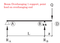
The first is a Simple Span Beam.

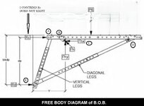
The second is a Bridge Bracket used on new bridge construction to form and pour the outer overhang such as gutter and guardrail areas. Note that I do not think reaction Rc is truly present and definitely not present on downward arm loads. The bracket has a single point load called P6. Trace the paths based on the letters shown at the joints and load application. Points B and E are the only 2 places where the bracket either mechanically attaches (B) or bears against (E) the bridge girder.
1752856082921.png


1752856103142.jpeg
 
so you could generalise this, once the students know your terminology ... here are a set of load forces, and here are the equivalent set of reactions ... that "equivalent" is an important concept. loadpaths link each load to each reaction (generally) ... you can show the "two force member" concept ... load and reaction are on the same line of action.

what education level are you teaching ? HS, college, uni ??
 
I am not teaching any level. I have briefly taught at a college when they got short-handed for a semester or 2. I run into students and recent grads periodically that ask me questions. I know people whose kids are in college, and sometimes one of their friends in engineering gets stumped. I like learning to describe things in a way they grasp concepts mentally before getting into calcs. I feel we jump to calcs way too quickly.

Also, as I get older, I do more refereeing, consulting or expert testimony. In legal, that is 13 or 1 matters, 12 jurors+1 judge, or just 1 judge. In refereeing, it is 2. Your Client and their opposition. If you can get the opposition to understand you better than they can understand their own engineer, your Client tends to fair better. I have had the other engineer explain a simple situation in a complicated fashion. I see their own client and mine confused. I then explain what he said back to my client, and I see the other guy's client nodding his head up and down in approval. So, at that point, don't blow it, your client is doing good.

In the last 10 years I have started emphasizing this concept more but I actually was exposed to it about 45 years ago. Only much later in my life did I realize the value in it but did not absorb at the time. I really struggled with electricity in physics. The day before a big test on something electrical, I was totally lost, could not grasp anything. Pretty much panicking. A friend's father was an Electrical Engineer that apparently did a ton or work in court cases. Power companies loved to hire him. Juries understood what he described. He met with me for about 75 minutes. I think we reviewed 3 chapters. He asked me about how quickly did class jump into calcs and heavy math. He told me that was a bad place to start learning. He started with something like your wheelbarrow scenario. He explained electricity like water hoses in a sense along with something about avoiding resistance. I left able to work all the problems without issue. I knew what to look for first, then how to organize. Did not study any more for the test. Shot pool and had a few adult beverages instead that night. Made a 97 on the test. Then I got stupid very quickly. I did not absorb the methodology he used to teach me. Instead, I remembered the way to solve those stupid problems, I would never need again. Within 6 months of getting out of physics, I could not remember what the electrical topic even was let alone with how to solve one.
 
Interesting. I completely agree about learning specific cases ... learn the general case, then you can solve any problem. Being able to get your ideas across to the audience d'jour is so super important. Have you seen any of the YT videos "I'm an expert" ... got to watch them ... like Dilbert, every one is so applicable to (at least) my work experience. I particularly liked when talking about red lines, the customer wanted them drawn with green ink; so the expert says "you can't", the PM jumps on him, and he explains wrapping up with "well, not everybody would notice the difference, some people a red/green colour blind, but I'm sure (he adds with a chuckle) that they are not your target audience." and this confuses the customer and gives them the rope "so, not everyone ...".
 
Oh yeah, I think IRStuff has a link to that one that I clicked on. I really enjoyed it. I did not know there were others. Gives me something to do for entertainment. I have actually been in a company meeting years ago when the PM showed us a rendering of the building we were going to do for a large Japanese firm. It was an in-house meeting of just employees. The salesman went crazy when he saw the building was green. Started chewing people out who did not have to answer to him. Screaming and pressing both hands to his temple while he shouted at us. It would have been humorous to record. This was years ago when a rendering was an actual painting.

Apparently, years prior to that he had a rendering of green building shown to a client that really hated green. Client got mad and went elsewhere. So his takeaway was NO MORE GREEN BUILDINGS. PERIOD. I asked him why not just ask the Client if there were any colors they preferred or that they really did not want. He thought that was not a solution better than no green buildings.
 
. learn the general case, then you can solve any problem.

That is the best way to learn for me. Get a feeling of what is going on first, learn the concepts, terminology, and steps to a final answer. Then you can solve any of the problems by applying that with some sound thinking. The students trying to learn by memorizing example problems may be setting the stage for overall failure. They must memorize thousands of example problems with a mental catalogue system that provides for retrieval. Won't happen. While it may be a good short-term system to get a passing grade in a class, it is not a good long-term one. You do not tend to forget what you absorb, but you can easily forget what you learn.
 
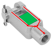
I had to color load paths/vectors on all FBDs starting in first-semester Statics, red for compression paths and blue for tension. One of the first examples I remember are linkage clevis/yokes, the question was why the "legs" can be so long without material in-between (ala the green block in the attached pic).
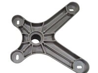
I agree that its a critical concept to understand, especially when you're trying to minimize material/weight like ribbed castings.
Screen Shot 2025-07-21 at 7.29.51 PM.png
image.jpeg
 
Last edited:
Was the vacant area with the green present so the threaded rod could extend into the location due to adjustment?
 
This is Part 2.
Since we have some basic definitions and 2 examples. To me, the next step is to see what we collectively use as ground rules or characteristics before getting into the "How to" part. The characteristics are harder to come up with than the "How to" part. The following is a preliminary list that I think are "somewhat accurate". I already know 13 can be argued either way. Even though I think they originate at the support, you get the same result working load to reaction method and the load to reaction is FAR easier.

So, for anyone interested, please help out.
  1. Load paths work for the loads from all sources (wind, gravity, seismic, thermal etc.) (many videos stated gravity loads but nothing else)
  2. Use DL = 0 for all components. The only time DL is not zero is if the force you are applying is the DL of a single item.
  3. Determining load paths is mostly a skill. It is a skill that requires a lot of head speed and head accuracy. If you learn the basics very well, they are easier.
  4. Load paths have different degrees of difficulty depending primarily on your objective. (This is here because I saw variations in what people considered the outcome to be of a completed tracing.)
    1. The basic level accounts for the reactions created by the applied load that are the same type as the applied load. In the Bridge Overhang Bracket [BOB], the applied load was a vertical point load. So on this level, we only want to know what vertical reactions are created by it. In this level you can have equilibrium but most likely not stability in all cases.
    2. The next level of difficulty, addresses all other reactions created by the load that are not like the applied load. In the BOB example, the 2 horizontal loads were not the same as the applied vertical load. In this level, we satisfy equilibrium and stability.
    3. The next level of difficulty is if you need to determine what deformations created the paths. In the BOB example, the following deformations/internal forces created the paths.
      1. The deformation was shear and moment in the beam that went from the point of application (C) to the support at B and the joint of the diagonal at D.
      2. Axial compression transferred the internal forces from D to E.
      3. Axial tension transferred the balance of the vertical force to A.
      4. The force then went from A to B as transverse shear in the cantilever beam AB.
    4. The next level is not always considered part of the load path arena but some may decide to mathematically solve the magnitudes of the reactions. In the basic sense, load paths do not require magnitude, just the path description and reaction designations (Fx, Fy, Mz etc)
  5. For purposes of learning, show every possible reaction at your foundations based on the type of foundation connection (Fixed, Pinned, Roller, Bearing etc). Even if the magnitude is found to be zero, leave the force arrow present but show the magnitude to be 0 if it is not needed.
    1. In other words, we contend there is a difference between a force not being possible (such as a moment at a pin) and therefore completely omitting a reference to it and there being the possibility of the force (a fixed connection) but the magnitude being zero. We want to see the force arrow with a magnitude of zero.
    2. Note: A bearing connection is like the one at E. It can only produce a reaction if the internal force pushes against the joint. If the internal force is away from the joint, there is no reaction possible.
  6. Load paths are almost instantly created upon the application of force to a structure.
  7. Only an EXTREMELY simple structure and loading has 1 load path. Most loads/structures have multiple load paths.
  8. A single applied force can create more than one load path. When it does, the magnitude of the “similar force” present in each of the paths will add up to equal the original force. The force in each path is not always equal to the initial applied force. Also, all reactions created that are not similar to the applied force should add to zero.
  9. The results of multiple load paths passing through a structural component are additive.
  10. Once an internal force gets a direct shot to a support capable of resisting it, it does not tend to change direction.
  11. The internal forces cannot “hop” to a location, it must travel by internal force or deformation.
  12. An applied force can travel the same load paths as other applied forces.
  13. While we tend to work load paths from the source of the applied force to the foundation reactions, we contend they are actually created going from the foundation reaction to the applied force. (Note: others may not agree with this but these concepts still apply). Basically, something has to refuse to allow the structure to "travel" for a path to get created. Working load paths from reaction to applied load is MUCH harder with no result that is better than the applied load to reaction method.
  14. The mechanism that predominantly determines the load path, is the deformations that are occurring due to the structures inability to “relocate” due to being tied to the ground with foundations.
  15. On a smaller level, the concept of load paths can be applied to the design of connections. They are especially helpful for connections with moments and torsion. While we tend to illustrate moments as if they function at a precise location, they are more “spread out” and are better represented by a “couple”. The following are examples:
    1. A steel I-beam connection has a couple created at the “general location” of the flanges. One flange is tension while the other is compression. The connection plate or interface tends to be perpendicular to the beam axis.
    2. A column that is embedded into the ground to provide the moment is actually a couple created by 2 bearing only forces. They are located on opposite sides of the column and at different elevations. They are located along the axis.
    3. A diving board is sometimes thought of as a fixed connection but in reality, it is an extreme example of a beam overhanging a support. The 2 reactions are fairly close to each other and the overhang is generally longer than typical. These 2 vertical reactions create the couple. They are space out along the axis.
    4. A concrete beam connection couple is the location of the centroid of the rebar (tension) and the centroid of the concrete compression area.
 

Part and Inventory Search

Sponsor

Back
Top