Eng-Tips is the largest forum for Engineering Professionals on the Internet.

Members share and learn making Eng-Tips Forums the best source of engineering information on the Internet!

  • Congratulations JStephen on being selected by the Eng-Tips community for having the most helpful posts in the forums last week. Way to Go!

Structure behaves as an arch or flexural member? 1

AK4S

Structural
Joined
Jan 2, 2015
Messages
103
Location
US
I am working on load rating of an existing bridge structure; a reinforced concrete arch built in 1902.

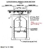
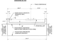
The structure has a short 7ft clear span with concrete profile, with 16” thick arch ring which encases 10” deep rolled steel beams spaced at 2ft on center spacing.

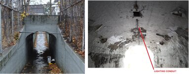
See attached sections of the bridge and representative photos.

(A). Based on the arch profile (with nominal surface reinforcement) it appears that the structure should behave like an arch and should be analyzed as an arch.

(B) However, the presence of the embedded steel beam makes me believe the original intent might be to treat it like a flexural member, so consider the steel beam as the main load carrying element and analyze as beam with fixed ends. Evaluate for the positive moment at mid-span which is WL2/24 for uniform load. The negative fixed end moment, WL2/12 will not govern since the depth of the structure at that location is significantly large (abutment walls).

Any thoughts on how the structure should be best analyzed, A or B? Would appreciate, if you could direct me to any references which would provide guidance on why a particular behavior is expected.

There were no significant cracks (only few minor hairline cracks) observed at the underside of the structure in the crown area.
 

Attachments

  • Cross section.jpg
    Cross section.jpg
    94.8 KB · Views: 45
  • Photos.jpg
    Photos.jpg
    391.8 KB · Views: 45
  • Transverse section.jpg
    Transverse section.jpg
    57.5 KB · Views: 45
I'd probably check both options A and B at least unofficially and include the worst case assumption in the official calc report to be checked unless the utilization is comparable then I'd include both options if utilization was high or "ok by inspection" if it was low. Probably not the answer you wanted...
 
Which load path is stiffer, the unreinforced arching concrete, or the encased steel beam? I don't think there is a direct answer, as the stiffness of the steel is dependent on the arch taking some load and preventing the encased steel from deflecting. But this might help you to think about how to address the problem.

Secondarily, which provides better behavior? Is failure of the concrete arch ductile? If it is not, would failure of the steel beam and bearing system behave with ductility? If there is some behavioral response you are targeting, perhaps that should be part of your consideration as well.
 
(A). Based on the arch profile (with nominal surface reinforcement) it appears that the structure should behave like an arch and should be analyzed as an arch.

(B) However, the presence of the embedded steel beam makes me believe the original intent might be to treat it like a flexural member, so consider the steel beam as the main load carrying element and analyze as beam with fixed ends. Evaluate for the positive moment at mid-span which is WL2/24 for uniform load. The negative fixed end moment, WL2/12 will not govern since the depth of the structure at that location is significantly large (abutment walls).

Any thoughts on how the structure should be best analyzed, A or B? Would appreciate, if you could direct me to any references which would provide guidance on why a particular behavior is expected.
Why do you have to choose A or B before you do the analysis? Can't you model it such a manner that the analysis will show you how the load is transferred to the supports?
I assume that you don't have access to the original calculations.
 
Why do you have to choose A or B before you do the analysis? Can't you model it such a manner that the analysis will show you how the load is transferred to the supports?
I assume that you don't have access to the original calculations.
I don't see a good way of modeling this combined A+B behavior in structural software. The arch would act as a 2D shell and the beam as 1D beam how would you connect the two. And what about boundary conditions since the shell would make up the beam element.
To be confident in the results you would probably need to use finite element software and model this whole thing in 3D space. I am sure there is no such budget for this thing.
I have no opinion about the avaiable budget. But load rating was mentioned and that can sometimes mean that one option is to replace the bridge. If you can "save" the bridge with a "better" analysis, it is usually very cost effective.

How to do this depends on the tools you have avaiable. And I don't see any good way to do this with 1D beam elements and 2D shell elements, I agree. But it also depends on the tool available.

But to model the I-section with shell elements and, at least initially, the arc (the concrete) with shell elements should work. It might be easier to model the arc with solid elements directly.

This may be a question of terminology but isn't a "structural software" also a "finite element software"? I don't quite understand the "can't be done" approach :) .
 
Fascinating.

Arch all day long for me owing to relative stiffness. If nothing else, imagine the damage that would have to be incurred in the concrete arch before the beam would kick in as any kind of simple span trabeate element.

At the least, I would start with assuming arch behavior as that's what I expect the true behavior to be. Migrate to weirder things as desperation requires.
 
I certainly think that it is prudent to be asking what the original designer's intent was for the beams. With beams at 2'-0" it was clearly a deliberate decision. Some alternatives:

1) OG designer didn't like / trust / understand arch action so they intended the beams to be the spanning element.

2) The beams had some temporary purpose as an aid to construction or something?

3) This is a Hail Mary but, perhaps, the model shown below?

01.JPG
 
I certainly think that it is prudent to be asking what the original designer's intent was for the beams. With beams at 2'-0" it was clearly a deliberate decision. Some alternatives:

1) OG designer didn't like / trust / understand arch action so they intended the beams to be the spanning element.

2) The beams had some temporary purpose as an aid to construction or something?

3) This is a Hail Mary but, perhaps, the model shown below?

View attachment 15922
KootK:
Thank you for your response. You definitely brought a few points on the table that I had not thought about.
1) OG designer didn't like / trust / understand arch action so they intended the beams to be the spanning element.
Not sure about this, but maybe they added the beams in case the arch starts to fail. But feel that's very unlikely.

2) The beams had some temporary purpose as an aid to construction or something?
To think about it, in case they had to carry loads before the backfill was in place to provide the required thrust for the arch action. So maybe at some phase before actual construction, the design team decided to add beams to cater to the temporary situation before the final condition (arch action with backfill in place). However with the current railroad track arrangement, I am not sure what kind of load would be there before the backfill was in place though. You need the backfill in order to place the tracks.

3) Could you elaborate a bit on the model you show.
 
Last edited:
I'd probably check both options A and B at least unofficially and include the worst case assumption in the official calc report to be checked unless the utilization is comparable then I'd include both options if utilization was high or "ok by inspection" if it was low. Probably not the answer you wanted...
Although I can perform a preliminary check on both options unofficially, unless one option absolutely fails or gives a very high utilization, will be difficult to convince someone on why the worst case assumption was selected, since I might be underestimating the capacity.
 
Which load path is stiffer, the unreinforced arching concrete, or the encased steel beam? I don't think there is a direct answer, as the stiffness of the steel is dependent on the arch taking some load and preventing the encased steel from deflecting. But this might help you to think about how to address the problem.

Secondarily, which provides better behavior? Is failure of the concrete arch ductile? If it is not, would failure of the steel beam and bearing system behave with ductility? If there is some behavioral response you are targeting, perhaps that should be part of your consideration as well.
The arching action would be stiffer I believe. But then what to do about the steel beams, they ought to have some purpose
 
Why do you have to choose A or B before you do the analysis? Can't you model it such a manner that the analysis will show you how the load is transferred to the supports?
I assume that you don't have access to the original calculations.
Yes, I don't have access to original calcs or design drawings from 1902, just sketches which were prepared by the team who did the NDT and field cores two decades ago to establish what the section looked like.

Not sure how I would go about to model the concrete encased steel beam in the arch shape to perform an analysis
 
3) Could you elaborate a bit on the model you show.

Maybe I know what you need here.

If the arch has thrust capability at it's supports, it can be in equilibrium without a midspan moment for which the concrete alone would unsuitable. Just axial load at the top. An arch doing archy things.

If the OG designer felt that the thrust reactions were questionable, they may have decided that it was best to have moment capacity at the midspan, per my sketch, in order to put the arch back into equilibrium.

Since the arch concrete alone was unsuitable for providing the midspan moment, maybe they stuffed the beams in there to do that particular job. So the beams would be doing beam-ish stuff right at midspan but would not be expected to develop meaningful curvature elsewhere.

Like I said, it's a Hail Mary.
 
It's also interesting that the wall reinforcing stops at the underside of the arch rather than continuing up to the beam. This creates the impression that we're meant to be doing the arch thing for that purpose. But, then, what turns the arch compression at the peak? DL? Or do you need the beams to provide midspan moment for this purpose as well?

01.JPG
 
Given the age of the structure, it's entirely possible that we are thinking about this much more deeply than the OG did.
 
Yes, I don't have access to original calcs or design drawings from 1902, just sketches which were prepared by the team who did the NDT and field cores two decades ago to establish what the section looked like.

Not sure how I would go about to model the concrete encased steel beam in the arch shape to perform an analysis
I did a very simple sketch to show you a possible approach. Only you can say if it is appropriate for you project, or not. But it doesn't have to be very complex.

A first step can be to model the concrete arc (green) and the steel beam (blue), see figure. Use an appropriate thickness to get a reasonable stiffness and load distribution. The red lines around the beam is some type of interface, rigid/friction/free. Based on this simple start you can push the modelling further with the correct beam section, solid elements for the concrete and so on.

But the main question is, is it worth it in this particular project?
 

Attachments

  • Eng-Tips_Beam.png
    Eng-Tips_Beam.png
    5.4 KB · Views: 3

Part and Inventory Search

Sponsor

Back
Top