Oengineer:
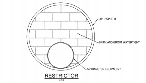
There is more to this problem than has been expressed yet. It seems to me that you need access to the inside of the 36” RCP pipe from above and an ability for an upstream cleanout system, at a given location. The upstream reach will collect grit and debris for lack of sufficient flow and might need regular cleanout. This probably means a manhole or access box of some sort. The access box could be cast concrete with the 14” opening on one side and the 36” RCP on other. In terms of the closure/restrictor structure, you might think in terms of a 4x4 (whatever size) stainless steel angle ring, probably in two halves for fit-up in the RCP, etc., which can be anchor bolter to the RCP, and can transmit the shearing load down the length of the pipe. Can this occur at a normal joint in the pipe, where we could weld shear lugs to the 4x4 angle ring which fit into the joint to transfer the shear loads in a more positive/uniform fashion? The closure wall can be several wythes thick, with one face (down stream) built as a tension wythe, maybe a round stl. pl. and other wythes as compression and moisture protection wythes, maybe even arching action if many wythes. The advantage of a masonry wall, as in old sewers, is that it is less susceptible to corrosion. There could be some sort of a bonded moisture membrane in the wall makeup. If this wall was at the manhole it could be cast concrete, with ability to remove forming from both sides, and a need for some top closure system over these two flow sides.
I would like to know more about why this restriction is needed. They are trying to limit the downstream flow for handling reasons during a sudden overloading, and have the storage capacity upstream? They are trying to increase the downstream flow velocity, at some normal depth, to transport solids downstream? You should talk with the hydraulics guys about this as it may influence the structural considerations or the shape of the 14” opening.