Continue to Site

Eng-Tips is the largest engineering community on the Internet

Intelligent Work Forums for Engineering Professionals

  • Congratulations The Obturator on being selected by the Eng-Tips community for having the most helpful posts in the forums last week. Way to Go!

Structural 3d Modeling- Theory help needed (AWC/ NDS- Deck) 1

WTT1

Structural
Oct 1, 2012
16
Hello all,

I'm hoping someone here can help me understand if I have modeled something correctly (Moment releases). Or if someone that has good experience can help me understand if the software is working in the way I would believe by intuition. I have little experience with these type software.

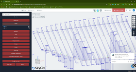
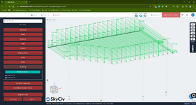
Below are screenshots of my situation. The issue is at the bottom center 45 degree bend.

In reality, I plan to use a double 2x12 as the rim joist and I plan to have member 76 tie into member 61 with a double skewed joist hanger. I have released all moments x,y,z at the end of member 61. The loading will be transferring from the left end of 76 into the joist hanger than is attached to the face of the end of 61

Is this the correct way to model this?

Also, i have one other concern and it is about "feel"/ bounciness etc.


This design is a little abnormal in that I have created an unsupported joint at the interface of 61 and 76. The distance from the left support post- 51- a 6x6 is 2.5', The distance form the right 6x6, 52, is 6'. 2x10 Joist are on 1' centers. The joist span is 14'. Post height 8'. (I hear, it is best practice to have a post at this joint. I would rather not because the post ends up being in the middle of a doorway sightline.-- this can be seen in the last screenshot section view)

How do I determine if I will have any bounciness? Can anyone here give any experience with these situations as I have none.

I have not done a code check on this design yet so I don't have the results of stress but I don't expect failures (maybe I'll be wrong). The displacement results are .325" max displacement at CL of joist. Rims show less than 1/16" displacement. (Some Rims show deflection in the positive direction. I assume that means I have uplift that I may have to account for with a post cap of proper resistance.
1747315190271.png
1747318080028.png
1747318115978.png
1747318393089.png
 
Replies continue below

Recommended for you

The deflections for the rims feels low.

Take a look at your moment and shear diagrams to see if things may have unintended fixity. Also plot the reactions and see if there are any spots with unintended support assignments.
 
It's a deck. Why on earth are you using 3d modeling?

Pick your longest joist and design it quickly by hand. If vibration is a concern, either use a higher load (60psf is not uncommon, especially if use a a rental property or frequent parties is reasonable) or a more strict live load deflection. I typically use L/480 for occupied floors.

Then size your girders. I like to set beams to L/600 for vibration sensitive floors, but L/480 is usually okay for decks.

Pick your hardware. Then size your ledger connection.

Then the more important parts - tension ties back to the structure and lateral load resistance of the deck. Ledger failures/pulling away, sway failures, and guard failures are the most common injury and fatality causing failures in decks. This one looks pretty tall, so make sure you pay close attention there.

Can anyone here give any experience with these situations as I have none.
Then you probably want to pull a supervisor or senior engineer in on it to get some direct guidance and project supervision.
 
Agree with phamENG you dont' need a 3d model for this. Joists @12"oc is going to get you laughed at by the contractor. Also, the existing header over the double door on the first floor will need to be checked for additional loading from the ledger.

Why does your model have an "unsupported joist"? I recommend you hand calc this framing to verify the output from the model.
 
The deflections for the rims feels low.

Take a look at your moment and shear diagrams to see if things may have unintended fixity. Also plot the reactions and see if there are any spots with unintended support assignments.
I will post screenshots of this shortly. I don't think I do. I do know I used a double 2x12 as the rim.
 
It's a deck. Why on earth are you using 3d modeling?

Pick your longest joist and design it quickly by hand. If vibration is a concern, either use a higher load (60psf is not uncommon, especially if use a a rental property or frequent parties is reasonable) or a more strict live load deflection. I typically use L/480 for occupied floors.

Then size your girders. I like to set beams to L/600 for vibration sensitive floors, but L/480 is usually okay for decks.

Pick your hardware. Then size your ledger connection.

Then the more important parts - tension ties back to the structure and lateral load resistance of the deck. Ledger failures/pulling away, sway failures, and guard failures are the most common injury and fatality causing failures in decks. This one looks pretty tall, so make sure you pay close attention there.


Then you probably want to pull a supervisor or senior engineer in on it to get some direct guidance and project supervision.
For the fun of it is honestly my answer. I don't get to do structural daily so it is enjoyable to me. I was thinking of using the L/480 as you were thinking and as of now based on my current constraints/ conditions.

I follow you on the girders and possibly L/600.

I also follow you there on the ledger connection hardware which I believe I have picked out properly.

I also follow you on the tension ties and guard failures. I do feel I have these things accounted for.

Essentially I was comparing my results to DCA 6 from AWC and was checking to see if I was in the ball park.

Do you agree with my assessment of the below:

"In reality, I plan to use a double 2x12 as the rim joist and I plan to have member 76 tie into member 61 with a double skewed joist hanger. I have released all moments x,y,z at the end of member 61. The loading will be transferring from the left end of 76 into the joist hanger than is attached to the face of the end of 61"

I'm assuming, the moment can't be transferred from the right side of the front 45 degree angle across to the left if I am using a joist hanger to tie member 76 into 61. But am I missing something?

I follow you on the "senior engineer", I don't work at a structural firm and this is a home project not being done for business purposes.

Just for enjoyment but I will be the contractor also.
 
Agree with phamENG you dont' need a 3d model for this. Joists @12"oc is going to get you laughed at by the contractor. Also, the existing header over the double door on the first floor will need to be checked for additional loading from the ledger.

Why does your model have an "unsupported joist"? I recommend you hand calc this framing to verify the output from the model.
Completely agree on the 3d model. I just used it because I felt like it. I hadn't got to use STAAD or any of the structural 3d modeling programs in a while so figured it would be a good time and I would learn some.

I'm the engineer and the contractor also. I'm not really laughing, just trying to get some guidance. :)

Thank you for the statement about the header over the door. The ledger is attached above the header to the truss that is running parallel to the backside of the house. This is not a new build. This is a "rebuild" of decks but a bit different than what was there when we purchased the house.

The joist is not really unsupported- My wording was not the greatest there. Essentially the floor joist are tying into the double 2x12 rim on the right side of the 45 and from there they tie into the rim on the left side of the 45 using a skewed joist hanger (simpson hanger intended for this condition).
---> I just wanted to make sure this concept doesn't need to be handled any differently --- I guess its just a girder tying into the end of another girder at this point. Nothing special and no moment can transfer across this connection due to the girder/ joist hanger?
 
The deflections for the rims feels low.

Take a look at your moment and shear diagrams to see if things may have unintended fixity. Also plot the reactions and see if there are any spots with unintended support assignments.
Thank you for being helpful. Yeeshhh. I get that models aren't necessary. I'm just trying to learn and have fun with this a little bit while also getting some conversation from people that do this as a career or at the least, know more than I do.

In terms of supports, Below is a screenshot of my support conditions, I did fixed at the column ends and a fixed line support at the ledger. All of these are taking out 6 degrees of freedom I believe it's called (no releases).

On all hanger connected joist (every floor joist) and the single girder (the one that ends with member 76 at the right side of the 45 on the front of the deck) that is connected by hanger (to member 61, left of the 45 angle). I have released moments in every axis.

1747334090606.png
1747334288249.png
1747334388589.png
 
Last edited:
Thank you for being helpful. I feel like I'm getting blasted a little bit on here. Yeeshhh. I get that models aren't necessary. I'm just trying to learn and have fun with this a little bit while also getting some conversation from people that do this as a career or at the least, know more than I do.

In terms of supports, Below is a screenshot of my support conditions, I did fixed at the column ends and a fixed line support at the ledger. All of these are taking out 6 degrees of freedom I believe it's called (no releases).

On all hanger connected joist (every floor joist) and the single girder (the one that ends with member 76 at the right side of the 45 on the front of the deck) that is connected by hanger (to member 61, left of the 45 angle). I have released moments in every axis.
The reason you may feel you are getting blasted is that this is about as simple of a beam structure as you will come across. You are getting the same advise from me I would give a junior engineer in my office. If you're unsure about your model output verify it by hand. If you are unable to run simple span beam calculations by hand you should learn how to do so. This isn't an attack simply good advise to learn structural engineering.

Regarding the fixed line at ledger. Why? Just add a pin support at that end at each joist.

Regarding a truss taking the ledger load. Are you checking to ensure that the truss is adequate for the new additional deck loading? Follow the load path to the ground.

Regarding joist hangers these are considered pinned connections unable to transmit moment.
 
Don't want to beat the dead horse, but that project does not need 3D modeling.
 
For the fun of it is honestly my answer. I don't get to do structural daily so it is enjoyable to me. I was thinking of using the L/480 as you were thinking and as of now based on my current constraints/ conditions.
Fair enough. I see in your other posts you're a DOT engineer?

I find your comment about using these programs as 'fun' to be a little...interesting. I don't enjoy them very much. Can be useful for streamlining stuff if you use whole packages (super structure, floors, connections, foundations) and all the accounting loads is handled under the hood, but that only comes after a lot of use. By hand and individual member design spreadsheets are my go to for most things until I'm dealing with several floors and large loads. But that's neither here nor there.

"In reality, I plan to use a double 2x12 as the rim joist and I plan to have member 76 tie into member 61 with a double skewed joist hanger. I have released all moments x,y,z at the end of member 61. The loading will be transferring from the left end of 76 into the joist hanger than is attached to the face of the end of 61"
I wouldn't call that a rim joist. It's a flush girder spanning form the end of 61 to the posts and then has a small cantilever. 61 is a girder with a central span and two cantilever spans. Semantics, but I think it's important.

And as for moment releases, correct. None of those are capable of transferring moment.
 
12" o.c. is a must when using trex decking. It's on every single job I do and 16" o.c. is a diving board after 2 years.

Bounce, L/18 (or less) on the joists and oversize the beams.
 
The reason you may feel you are getting blasted is that this is about as simple of a beam structure as you will come across. You are getting the same advise from me I would give a junior engineer in my office. If you're unsure about your model output verify it by hand. If you are unable to run simple span beam calculations by hand you should learn how to do so. This isn't an attack simply good advise to learn structural engineering.

Regarding the fixed line at ledger. Why? Just add a pin support at that end at each joist.

Regarding a truss taking the ledger load. Are you checking to ensure that the truss is adequate for the new additional deck loading? Follow the load path to the ground.

Regarding joist hangers these are considered pinned connections unable to transmit moment.

I follow you about verifying the model by hand. I can do that. For me, it was more about assumed "theoretical" conditions vs. how the real world actually functions. With no real world experience, I just wanted to make sure I wasn't making an inaccurate assumption about the way a connection etc functioned.

On the fixed line at the ledger. Because the software had the option. No reason other than that. I could see how the pin idea would probably be more useful in the end- and potentially more simplistic. I actually haven't looked at the reactions generated at the "line" to see what the software even did. I assume it summed all of the reactions and gave them at the centroid of the line but I don't know yet.

Yes, I will be checking to ensure the truss will suffice. That is on the horizon but I'm not there yet. (There was an existing deck that had survived since 1987 so it will be a check more for myself and completion/ code sake more than for actual physical concern)

Thank you for the information on the joist hanger.
 
12" o.c. is a must when using trex decking. It's on every single job I do and 16" o.c. is a diving board after 2 years.

Bounce, L/18 (or less) on the joists and oversize the beams.
Yeah, I'm not sure where that one comment came from.

And I'm using AZEK pvc so it is in the same idea you are speaking from.

Thank you for the information on the joist/ beams.

For the joist, in my case. It looks like L/480 has been met.

For the Beams/ Girders. I have very low displacements. Probably much lower than L/480 but I haven't ran the ratio.

Thank you again for the constructive information!
 
Fair enough. I see in your other posts you're a DOT engineer?

I find your comment about using these programs as 'fun' to be a little...interesting. I don't enjoy them very much. Can be useful for streamlining stuff if you use whole packages (super structure, floors, connections, foundations) and all the accounting loads is handled under the hood, but that only comes after a lot of use. By hand and individual member design spreadsheets are my go to for most things until I'm dealing with several floors and large loads. But that's neither here nor there.


I wouldn't call that a rim joist. It's a flush girder spanning form the end of 61 to the posts and then has a small cantilever. 61 is a girder with a central span and two cantilever spans. Semantics, but I think it's important.

And as for moment releases, correct. None of those are capable of transferring moment.

Yeah, I work on the construction side so there aren't many calculations going on. Out of school, I worked for a place that designed the structure for power plants for 5 years or so. All steel work. (PE in 2010).-- But since 2011, I've been at the DOT.

"Fun" is most definitely an overstatement on my end. It has been annoying :) but I'm just taking this as a learning experience. I can definitely see how this would not be the path forward for this project if it was being done for "production" and to make money. In my instance, I'm just doing it for the experience of using the software.

Thank you for the semantics statement. I agree it is important. I was talking very generalized in my original post but I can definitely see the value in proper semantics.

Thank you for the information about the moment releases.

I am at the point in the software now where I have ran into another roadblock before doing the code check. It is the "Effective Length of Bending Members"- Le. In NDS, table 3.3.3 has common cantilevers/ simple spans so that a table result can be pulled to calculate Le. This works great for the joists and makes quick work of them. For the girders however, I don't think I understand how to proceed. Theoretically I understand what I have (detailed below). I also have looked at a document called TR14 from AWC which is a generalized procedure for calculating Le for any beam layout.

Left girder: cantilever, span, cantilever with distributed load across all and point load at far right side which will be in the magnitude of the far left support from the girder spoken of below.

Right girder: span, span, cantilever with distributed load across all

Could you all comment/ give me some direction on my situation regarding Le for the girders.

I am going to go ahead and get my moment diagrams ready for each girder. At that point, I don't really understand how to use them to apply TR14 for Le.

This same section of the software starts asking for all of the "C" factors for the different types of stress, I think I can muddle through this area using the code without much problem but we will see.
 

Attachments

  • AWC-TR14-0312.pdf
    467.8 KB · Views: 2
Last edited:
I signed up for skyciv about 6 months ago. It's actually very nice. $100 a month and does a ton of designs. Latest is full steel detail connection designs with illustrations. For the price, I don't think anything compares on the market.

Fixed, or not fixed, on wood joists though, you'll get a 2x6 working spanning 16' if you fix the supports. And that would be a very flawed result. Unless you embed wood in 2' of concrete, it's pinned.
 
12" o.c. is a must when using trex decking. It's on every single job I do and 16" o.c. is a diving board after 2 years.

Bounce, L/18 (or less) on the joists and oversize the beams.
I hear people say that but I have used it on 5 personal projects with 16"O.C. joists - 2 which are over 20 years old and it has never sagged or felt bouncy.
 
I hear people say that but I have used it on 5 personal projects with 16"O.C. joists - 2 which are over 20 years old and it has never sagged or felt bouncy.
It was first relayed to me by a contractor who builds mostly decks. Roof top and regular. I have 2 investment properties with trex decking, one was built at 24 oc, 1 at 16. Forget about 24, you can see the banana, the 16 feels very soft. Not like a conventionally framed deck with 1x planks, much more bounce.
 
It was first relayed to me by a contractor who builds mostly decks. Roof top and regular. I have 2 investment properties with trex decking, one was built at 24 oc, 1 at 16. Forget about 24, you can see the banana, the 16 feels very soft. Not like a conventionally framed deck with 1x planks, much more bounce.
Weird, I have never noticed any unpleasant bounce with my composite decking. FYI, most wood decking is 5/4 not 1x (at least in my area).
 

Part and Inventory Search

Sponsor