Hello all,
This is the first post I have added here. Maybe it will help someone in the future and myself in the near term. I'm a civil engineer (PE) for the DOT so I have a bit of educational knowledge but 0 real world knowledge in the subject I'm posting about. Essentially, I have read so much at this point, that I've probably confused myself more than anything-- I have taken a theoretical approach also because I would like to learn more about how real world works in situations with much more substantial loading.
Below I will give all of the things I have determined about my situation. I will be the engineer and the construction worker on this process.
Loads:
10 psf dead
40 psf live
It looks like the service load per post is 3000 pounds based on the above.
I am in Knoxville TN; Seismic Design Cat. C
90mph asd wind, 115 vult wind
deck (foundations) 6x6 post on 10' centers; The deck is 12' transverse to the back of the house (30' parallel to the house)-- again post on 10' centers
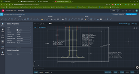
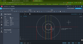
circular foundation's base will be at 2' below the ground surface, it will be 1' thick and 2'x2'
The stachion/ pier/ column that goes down to the base will be 15" long (3" of which will be above the ground)
The "column" will be made by a 12" circular sonotube.
I have learned through ASCE 7 wind/ uplift calcs that I have no net uplift on the edge post nor center post.
I have also learned that I believe the pier/ stanchion/ short column could be calculated based on "plain concrete"-- the 3:1 ratio-- maybe I'm wrong?
I think I have also learned the footing doesn't need rebar by theoretical calculation but I have heard its a good idea.
I plan on putting 3 #4 rebar in, in each direction and tying together with rebar ties, they will be 3" up from the foundations base (12" total thickness).
If I'm understanding correctly, in my situation, the rebar in both the pier and the footing is somewhat "insurance" and good practice for the potential of seeing tension through ground movement/ crack mitigation etc.
But...
Here are the areas I'm confused:
I feel like I need to tie the 12" column to the to the base with rebar but I'm confused if I need to have the bends on the bottom of the main bars to tie them into the rebar that will be 3" up from the base of the foundation. I feel like I've read in the CRSI handbook (1956- freely available) that Case 4 is using only straight dowels as no moment would be transferred in my instance. However their table calculations don't go down to a 2x2 footing and they don't specify a case 4 dowel bar size as you start getting into the smaller sized footings and I don't really understand why. Can someone with more knowledge than me extrapolate this just from experience?
Also, if I do put the 90 degree bend on the portion that is in the footing, do I turn the bends in towards each other or away from each other. Also, do the bends sit on top of the other rebar that is 3" up from the base of the footing and tie in with the wire or do I hook them under that rebar. With my column size being 12" and my footing being 24"x24", I don't know that the 90 degree bends matter as I don't see how there's much bending here due to the proportions.
Also, I'm confused on the need for column ties. I understand what they do but do I need them in this case? In small load situations like this, how do you know where you can "make liberal modifications" or where you need to stick to the code? (I know experience helps, but I don't have this in this area of engineering) :-/; I guess if I'm working off of the "plain concrete" section of aci 318, I guess they aren't need at all, again only if practical to help with construction/ not necessarily engineering calcs for code compliance)
I know my loads are small and the ties apparently help with resistance to buckling of the main/ longitudinal steel reinforcement of the column and confinement of the concrete core.
I was looking at compression developed length to help understand this dowel concept (I feel like their related but don't know/ understand fully). I feel like this idea relies on the bond strength of the concrete to the surface area of the rebar available with no 90 degree bends at the base of the main column steel (as spoken of 4 paragraphs above).
Could you all give the theoretical explanation surrounding my confusion above and then give me the "you're overthinking things, here's what I would do based on what you already know explanation".
Last edited:


