Tek-Tips is the largest IT community on the Internet today!

Members share and learn making Tek-Tips Forums the best source of peer-reviewed technical information on the Internet!

  • Congratulations cowski on being selected by the Eng-Tips community for having the most helpful posts in the forums last week. Way to Go!

Stepped column - AISC DG 7

Status
Not open for further replies.

BAGW

Structural
Joined
Jul 15, 2015
Messages
392
Location
US
Hi,

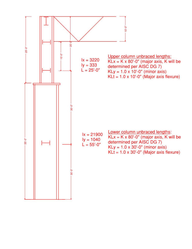
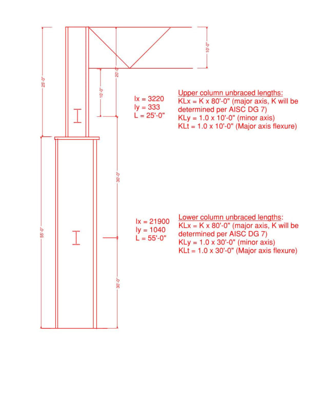
I am trying to understand the the effective length factors for stepped column per AISC DG 7. See the attached image.

The struts needs to be at the location shown. Based on the strut locations, is my unbraced length for the axial and flexure calculations correct. The "K" factor for the major axis will be determined per Appendix B of AISC DG 7.

The only thing that is throwing me off is not having a strut at the top and bottom column intersection. I cannot have a strut there because of clearance requirement and hence I have thrown a strut at 60'-0" elevation. So I am not sure if the unbraced length that is shown in the figure for the minor axis buckling is correct. Any inputs will be appreciated.

Document2_kgdlyc.jpg
 
Since your upper strut is located above the location where the column size is reduced, the unbraced length in the minor axis between the upper and lower strut will need to account for the column size change. Fortunately, though, this is what Appendix B of AISC's Design Guide 7 shows you how to do. You would just use the same approach as you are already doing for the major axis, but do it for the minor axis using a total length of 30 feet with pinned-pinned supports.

Also, the bottom flange of the roof truss likely does not brace the column for minor axis buckling unless you have some bridging there.

Structural Engineering Software: Structural Engineering Videos:
 
I have bridging in the bottom chord level.

So for the minor axis, do I use Length of the upper and lower shaft between the struts. For instance in my case the L1 = 5'-0" and L2 = 25'-0". And for flexure I can use the same K1 and K2 obtained for minor axis correct?
 
Yeah, that's how you would determine the K1 and K2 values for the region between the two struts. You use them to determine the compression capacity for minor axis buckling (not flexure).

It may also be helpful to know that the examples in the 2nd Edition of Design Guide 7 are based on equations that come from the 1989 ASD Specification. The interaction equations have P-delta effects built into them.

The 3rd Edition of Design Guide 7 was released in 2019 which uses the 2016 Specification. In it, they changed the recommended procedure so that you capture the second order effects and K factors for the stepped column by using a computer model.

Structural Engineering Software: Structural Engineering Videos:
 
How do I determine unbraced length for flexure then? I looked at the DG examples and seems like they have a strut at the intersection.

What will be the unbraced length for the flexure? Is it straight strut to strut spacing? Or can I use the above and below column intersection?
 
You need to show where the out-of-plane restraints are, and what they are (so stiffness can be judged). Those are what determine these effective lengths. In the first diagram, you only showed the two I-beams on the column centreline but in the responses you say there is other bracing.

For bending effective length, also need to know which flange is in compression along the length.
 
I have those two struts shown in the diagram. At the bottom chord I have another member. The struts are designed for torsional stiffness along with their connections. The connections are detailed such a way that both the flanges are braced.

Document2_yg3wva.jpg
 
Ok thanks
 
Status
Not open for further replies.

Part and Inventory Search

Sponsor

Back
Top