Continue to Site

Eng-Tips is the largest engineering community on the Internet

Intelligent Work Forums for Engineering Professionals

  • Congratulations 3DDave on being selected by the Eng-Tips community for having the most helpful posts in the forums last week. Way to Go!

Stepped Footing Design

KristenAellen

Student
May 28, 2025
3
So I am a structural engineering intern and i am trying to design a stepped footing for a wall. I know how to design a footing but when it comes to a stem wall or stepped footing, I'm lost. It seems like there's no design books for stepped footings or a stem wall. I'm currently designing a footing for a temp bridge and they sent us preliminary drawings but I have no idea how to tell if its okay or not. Any help would be great! Thanks!
 
Replies continue below

Recommended for you

Building codes typically have guidelines on max vertical rise over run. But typically for bridges you will have a construction joint at the step. AASHTO should provide guidance if you have access to the code. Some details will show an actual step and others will slope the bottom. Not really sure it’s worth stepping a footing for a temporary structure. As for actual design I am not aware of anything special to the steps itself. Footing of this nature are designed in unit lengths so length wise the reinforcement is really temperature and shrinkage steel. Alternatively tee walls might be more appropriate for this type of work, they just use a leveling pad, you can check out their standard details. I think PA dot has good details. Maybe share more info on what the step is like and the structure that sits on it. As an intern I would hope you can also ask this from your manager or coworkers, but also know that doesn’t always workout. But good on you for seeking knowledge and taking initiative.
 
Building codes typically have guidelines on max vertical rise over run. But typically for bridges you will have a construction joint at the step. AASHTO should provide guidance if you have access to the code. Some details will show an actual step and others will slope the bottom. Not really sure it’s worth stepping a footing for a temporary structure. As for actual design I am not aware of anything special to the steps itself. Footing of this nature are designed in unit lengths so length wise the reinforcement is really temperature and shrinkage steel. Alternatively tee walls might be more appropriate for this type of work, they just use a leveling pad, you can check out their standard details. I think PA dot has good details. Maybe share more info on what the step is like and the structure that sits on it. As an intern I would hope you can also ask this from your manager or coworkers, but also know that doesn’t always workout. But good on you for seeking knowledge and taking initiative.
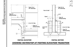
Honestly I don't see the point to stepped footings. It just seems like its complicating things for nothing. It would be easier to just do a normal footing and stem wall. I did get some guidance yesterday from a colleague. He said to design the stem wall as a wall, the stepped footing as a pier and the footing as a footing. I believe that makes a bit more sense to split it up and design it that way but i think for me, I am going to design a stem wall and footing and see what sizing and reinforcement I get to see if its similar at all to what they have designed. Thank you for your help though.
 
The procedure is similar to that of the normal wall footing however, at every step you have to ensure that the one way shear at the step is within allowable limits. You can check that with the help of code formula.
 
Can you provide a sketch? Maybe you need to consider lateral earth pressure on the vertical steps, which is a pretty complicated calculation if you ask me. It involves calculating surcharge pressures with something like a Boussinesq distribution and calculating the resulting moment, which is not something an intern should be doing. Maybe I'm overcomplicating things and will calm down once I see a sketch.
 
This is the design I was given by not my company. They want me to design a footing and I believe essentially check to make sure its okay. The dead load given for the bridge was 40Kips so 20 to each side and smearing it on the footing of 24'-3". I have done some work and found I need a 34" footing with a d of 30.5" and the q is 3ksf at 3' below the surface so I'm having a 3' stem wall. Haven't done any design on that yet though. Since I don't know how to design a stepped footing, I am just doing a normal footing and stem wall based on AASHTO.
 

Attachments

  • Bridge support Details.pdf
    51.2 KB · Views: 13
Hopefully you do not have too many steps in your wall. On very long walls they can save money but on short walls (20ft or less), then I think they are more trouble than they are worth. The contractor has a more complicated form setup and has to do multiple pours usually.

With that being said.....TxDOT has a stepped wall detail. I do not think there is any structural analysis or calculations behind it. They just connect the two footings.

Whenever I do steps, I keep the step size small (less than 4ft); and I look at the geotech report to make sure I'm not crossing between two radically different soil strata. I also put an expansion joint in the wall above.

TxDOT Misc. Retaining Wall Details.......

chrome-extension://efaidnbmnnnibpcajpcglclefindmkaj/https://ftp.dot.state.tx.us/pub/txdot-info/cmd/cserve/standard/bridge/RW-SF-25.pdf

1748530461257.png
 

Part and Inventory Search

Sponsor