tkd77
Structural
- Jan 30, 2020
- 5
Hi All,
Some advice needed - primarily to confirm if I am overthinking something I have never worried about before. I work for a large precast producer, who often makes very long, slender columns.
Two considerations often govern the unit checks that we perform.
A) We often have to specifically check for the pitching/tilt lifting case (we operate in the architectural market, so nearly always have to pitch lift from the end (top as installed) of the column as clients do not want lifter recesses on the side face. Whilst the ultimate limit state design is nearly always satisfied by the permanent works rebar specification, we often end up increasing main bar dia and/or overall steel area to limit crack widths.
The query here is whether it is correct to assume an average stress in the reinforcement for the crack checks (i.e. to calculate the tensile stress by a simple force/bar area check). As the main bars are typically different diameters (i.e. we might have B25 in the corners, but B16 in the centre of the face) I often wonder whether we should be proportioning the stress at serviceability limit stage according to the relative axial stiffness of the bar (i.e. using AE/L for the specific bar - which typically cancels to just the A). Thoughts please.
B)Often these are double storey or triple storey columns, and often have a physical void at the floor levels (e.g. a double height column would effectively be two smaller columns but produced as a single member with the main reinforcement running through the void. This section of the reinforcement is designed to prevent a combination of compression buckling and local moment at ultimate limit state - both for the pitching case, and the case when installed when it effectively takes the compression load from the upper sections of the column.
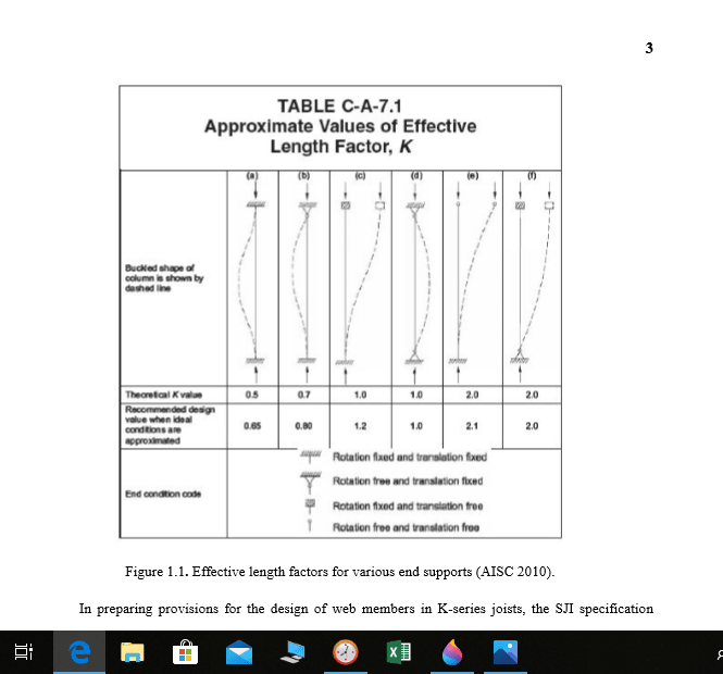
Prior to me taking over, standard practice in calculating the compression buckling capacity was to assume an effective length of 0.7 x the bar length between the concrete sections. I have since changed this to 1.5x the bar length between the end links in the concrete sections during pitching(on the basis that this section effectively behaves as in a semi-sway or sway type mode - i.e. like a truss where the central bay works on vierendeel truss principles) and between 1.5 and 2 for the case when installed (as overall column curvature is that of a cantilever). Am struggling to find any formal or written justification for this method - the only thing I can think of is using a frame effective length coefficient method similar to that found in appendix D and E of BS5950 - but setting the beam values to zero to effectively treat these bars as a compression member of two different section sizes and restraint conditions. Have used this in the past to analyse very old portal frame columns where the column is supporting a gantry crane and formed of two different UB sections. Thoughts on this welcome..... see sketch attached.
Some advice needed - primarily to confirm if I am overthinking something I have never worried about before. I work for a large precast producer, who often makes very long, slender columns.
Two considerations often govern the unit checks that we perform.
A) We often have to specifically check for the pitching/tilt lifting case (we operate in the architectural market, so nearly always have to pitch lift from the end (top as installed) of the column as clients do not want lifter recesses on the side face. Whilst the ultimate limit state design is nearly always satisfied by the permanent works rebar specification, we often end up increasing main bar dia and/or overall steel area to limit crack widths.
The query here is whether it is correct to assume an average stress in the reinforcement for the crack checks (i.e. to calculate the tensile stress by a simple force/bar area check). As the main bars are typically different diameters (i.e. we might have B25 in the corners, but B16 in the centre of the face) I often wonder whether we should be proportioning the stress at serviceability limit stage according to the relative axial stiffness of the bar (i.e. using AE/L for the specific bar - which typically cancels to just the A). Thoughts please.
B)Often these are double storey or triple storey columns, and often have a physical void at the floor levels (e.g. a double height column would effectively be two smaller columns but produced as a single member with the main reinforcement running through the void. This section of the reinforcement is designed to prevent a combination of compression buckling and local moment at ultimate limit state - both for the pitching case, and the case when installed when it effectively takes the compression load from the upper sections of the column.
Prior to me taking over, standard practice in calculating the compression buckling capacity was to assume an effective length of 0.7 x the bar length between the concrete sections. I have since changed this to 1.5x the bar length between the end links in the concrete sections during pitching(on the basis that this section effectively behaves as in a semi-sway or sway type mode - i.e. like a truss where the central bay works on vierendeel truss principles) and between 1.5 and 2 for the case when installed (as overall column curvature is that of a cantilever). Am struggling to find any formal or written justification for this method - the only thing I can think of is using a frame effective length coefficient method similar to that found in appendix D and E of BS5950 - but setting the beam values to zero to effectively treat these bars as a compression member of two different section sizes and restraint conditions. Have used this in the past to analyse very old portal frame columns where the column is supporting a gantry crane and formed of two different UB sections. Thoughts on this welcome..... see sketch attached.
")