MatthewLynch
Mechanical
Hi, I have an assignment where I have to calculate the optimum spacing of spot welds of a simply supported built up beam that is made with a C channel and two plates welded one on top and one under that has a uniformly distributed load on top of it. Each spot weld can take 8kN of force, and to calculate the spacing I used
 and integrated in the length of the beam. Once force reaches 8kN my spot weld is placed at the center of that distance.
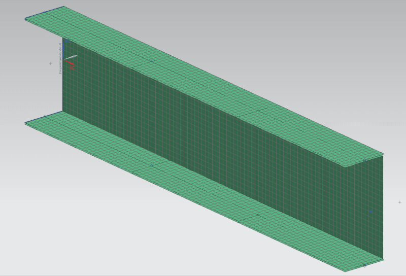
My mesh is done with CQUAD4 elements and to represent the welds I am using CBAR elements that join two nodes of the mesh. The problem I am finding is that the force on the spot welds are allow lower than what I have calculated. So I tried with a more simplified model.
This more simple model is a shorter cantilevered beam. Length is 900mm and it has spot welds every 300mm (so one at 300, one at 600 and one at 900). I have tried applying a load at the tip and also distributing the load on top of it, but I still get wrong results. For example, for the point load at the end I am getting 328N at first point weld, 439N and 189 N at second and third point. But according to my math, these should be 586N, 586N and 293N. If I also apply a torque to compensate for the load not being on shear center the difference gets smaller, but is still very large (400N,544N and 260N).
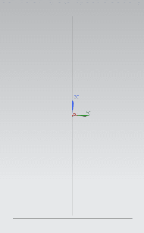
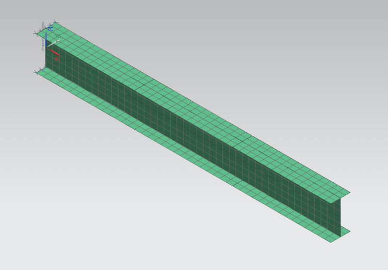
So I then went to try another simple model with a wide flange beam where the flanges are welded to the web with spotweld (same length and same location of spotwelds). With this beam and a point load on the tip results are much better. The errors compared to my analytical solution are 10.95%, 0.74% and 2.56% (all forces on points on FEA model are lower than the analytical). The first spot weld with much higher error I think is because of effects of the boundary condition taking higher load that what I calculated. But the second spot weld get quite accurate results. But when I apply a distributed load over the wide flange beam I get a larger error.
For a cantilever beam with uniformly distributed load
 and then integrating between two length I get

With this my FEA model is getting forces that have an error of 16.5%, 4.15% and 89.46% (in this case the FEA results for first spot weld are lower than analytical solution, but for second and third spot weld they are higher). Why would the error increase when I have a uniformly distributed load?
I see the same for the beam made with C channel, when uniformly distributed load is applied error is much higher than with point load. And also I do not know why there is such a difference between the wide flange beam and the C channel build up beam. Is there something I am forgetting to consider for my analytical solution in the C channel beam? I have tried applying load in shear center but still get wrong results.
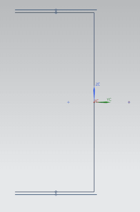
These are some photos of my models


As final comment, my expected results were that I should have the same, or very similar forces in the direction of the shear flow and a new force perpendicular caused by the torsion of load not being in shear center. And the resultant force should be larger than the one I had calculated

My mesh is done with CQUAD4 elements and to represent the welds I am using CBAR elements that join two nodes of the mesh. The problem I am finding is that the force on the spot welds are allow lower than what I have calculated. So I tried with a more simplified model.
This more simple model is a shorter cantilevered beam. Length is 900mm and it has spot welds every 300mm (so one at 300, one at 600 and one at 900). I have tried applying a load at the tip and also distributing the load on top of it, but I still get wrong results. For example, for the point load at the end I am getting 328N at first point weld, 439N and 189 N at second and third point. But according to my math, these should be 586N, 586N and 293N. If I also apply a torque to compensate for the load not being on shear center the difference gets smaller, but is still very large (400N,544N and 260N).
So I then went to try another simple model with a wide flange beam where the flanges are welded to the web with spotweld (same length and same location of spotwelds). With this beam and a point load on the tip results are much better. The errors compared to my analytical solution are 10.95%, 0.74% and 2.56% (all forces on points on FEA model are lower than the analytical). The first spot weld with much higher error I think is because of effects of the boundary condition taking higher load that what I calculated. But the second spot weld get quite accurate results. But when I apply a distributed load over the wide flange beam I get a larger error.
For a cantilever beam with uniformly distributed load


With this my FEA model is getting forces that have an error of 16.5%, 4.15% and 89.46% (in this case the FEA results for first spot weld are lower than analytical solution, but for second and third spot weld they are higher). Why would the error increase when I have a uniformly distributed load?
I see the same for the beam made with C channel, when uniformly distributed load is applied error is much higher than with point load. And also I do not know why there is such a difference between the wide flange beam and the C channel build up beam. Is there something I am forgetting to consider for my analytical solution in the C channel beam? I have tried applying load in shear center but still get wrong results.
These are some photos of my models


As final comment, my expected results were that I should have the same, or very similar forces in the direction of the shear flow and a new force perpendicular caused by the torsion of load not being in shear center. And the resultant force should be larger than the one I had calculated
