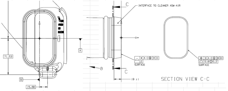
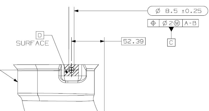
I have a Blow Molded part with A & B datum given as center point of a Slot. This slot opening does not have any inner dimensions but only profile callout on the outside since it is assembled in a housing. Now, I am working with one of our Gauge manufacturers who is asking if this is at RFS or MMC. To my understanding, it is at RFS, but I am not able to think of a way to lock datums A &B. I am attaching a sketch, can you guys help me with how to lock datums A & B in a checking fixture.
Tek-Tips is the largest IT community on the Internet today!
Members share and learn making Tek-Tips Forums the best source of peer-reviewed technical information on the Internet!
-
Congratulations JAE on being selected by the Eng-Tips community for having the most helpful posts in the forums last week. Way to Go!
Slot as Primary datum for a Blow Molded Part
- Thread starter MPSU
- Start date
Similar threads
- Locked
- Question