Hello, I'm back again.
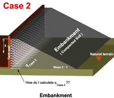
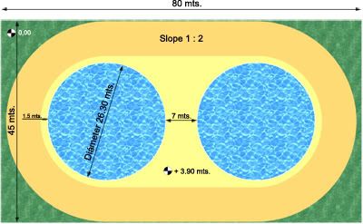
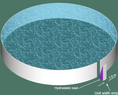
I'm having a difficult time estimating active and passive pressures from the sloping backfill for a project I'm currently working on. The project consists of two neighboring circular concrete tanks (Height=4.16m, Inner Diameter=26.10m, Wall Thickness=0.10m) with a compacted external embankment. As both tanks are identical, I've limited to only one of them the following study of the pressures involved.
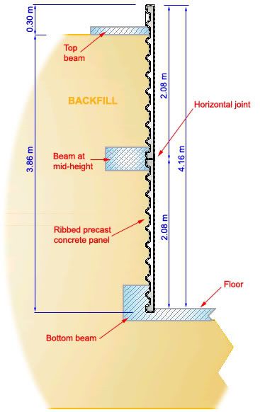
The wall cross-section is like so:
And the backfill is implemented like this:
Cross-section:
Isometric view:
I'd need clarification on some conceptual points that I don't fully grasp.
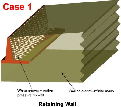
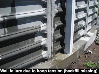
Earth backfill is what makes the whole system structurally sound. Precast panels are not stiff enough on their own to resist hoop tension or vertical bending moments. That's why the backfill becomes mandatory.
[tab]
Sidenote:
See what happens when the contractor "forgets" to do the backfill:
Now to the calculations, could you please confirm if the following reasoning is correct?
Passive Pressure
==========
When the tank is filled, the backfill has the potential to counteract internal water pressure up to a maximum given by the passive pressure.
- OR -
To counteract hydrostatic load, the backfill can contribute a pressure whose upper limit is the value of the passive pressure.
From ufc_3_220_10n.pdf, a "Unified Facilites Criteria" on Soil Mechanics by the Naval Facilities Engineering Command, page 223:
5. PRESSURE ON VERTICAL SHAFTS.
a. Shaft in Sand. In the excavation of a vertical cylindrical shaft granular soils, pressures surrounding the shaft approach active values. If outward directed forces from a buried silo move the silo walls into the surrounding soil, pressures approach passive values as an upper limit.
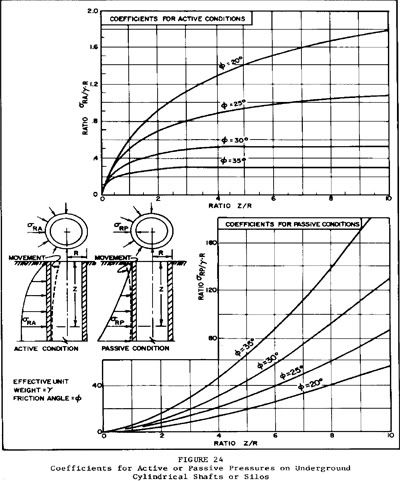
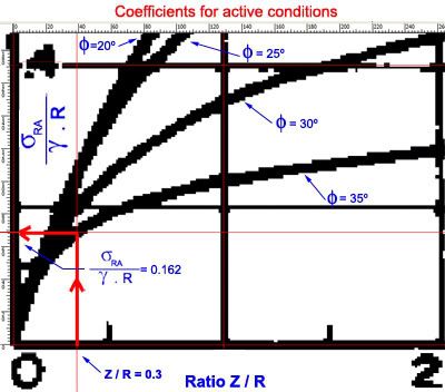
(1) Pressure Coefficients. See Figure 24 for active and passive pressure coefficients for a cylindrical shaft of unlimited depth in granular soils.
(2) Modification of Active Pressures. For relatively shallow shafts(depth less than twice the diameter), rigid bracing at the top may prevent development of active conditions. In this case, horizontal pressures may be as large as at-rest pressures on a long wall with plane strain in the surrounding soil. (See DM-7.2, Chapter 3.)
[attn]Reference:[/attn]
ufc_3_220_10n.pdf can be downloaded
here.
So, if I'm on the right track I can use Figure 24 from that document to estimate the passive pressure that the wall would have to apply to the earth mass for the whole system to fail.
[φ] = angle of internal friction = 35º (backfill is a sandy soil ==> cohesion = 0)
[γ] = soil bulk unit weight = 1900 Kg/m
3
R = external radius = 13.15 m
Z / R = 3.86 / 13.15 = 0.3
Then, from the passive pressure graph I get [σ]
RP / ([γ] . R) = 3.25
I must admit shallow cylinders like this tank configured an edge case for the graph author. I had to zoom-in and place rulers to get as accurate a reading as possible. (I don't know how valid the readings are for edge cases like this).
Anyways, going ahead: [σ]
RP = 3.25 x 1900 x 13.15 = 81,201 Kg/m
2
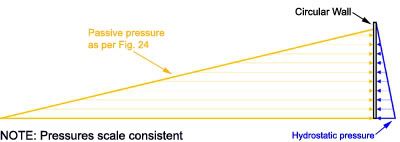
Here is the pressure diagram (scale consistent):
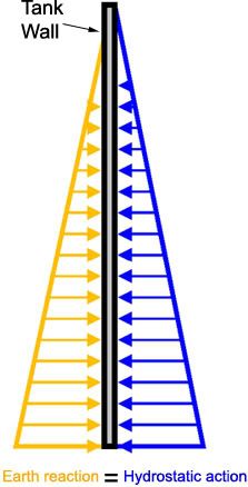
Obviously, by no means can the earth reaction be any different than the hydrostatic action. That was just an upper limit. It's as if the soil said
"if needed, I can respond with pressures up to 81,201 Kg/m2". In other words, that number cannot be used in the calculations. When the system is in equilibrium, the actual diagram would tend to honor Newton's third law. Simplistically:
However, these 81,201 Kg/m
2 are half of the story. This number explains failure from the soil's point of view only. I think Figure 24 assumes that the underground cylinder can deform elastically whatever magnitude is necessary to push the surrounding soil up until 81,201 Kg/m
2, the threshold that produces the soil's failure. That's not the case of a concrete wall. It's deformations what triggers concrete failure, not the stresses in the soil mass.
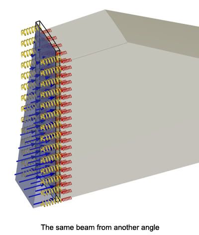
Let's see it from another angle:
Theoretically, the role of the sloping backfill in a thin-walled concrete circular reservoir is to prevent wall deformation, and thus the development of hoop tension and vertical bending moments that crack the concrete.
However, the more I think about this problem, the more complex the analysis gets (at least for me).
Let's rule out backfill for a moment.
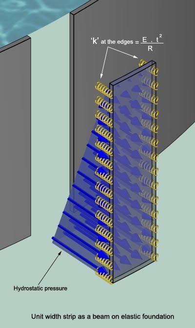
The specialized literature on tank design treats a circular wall subjected to hydrostatic pressure as a beam on elastic foundation. A strip of unit width is isolated and analyzed.
For the simple case in which
no backfill is involved, the modulus of the foundation 'k' is E . t
2 / R and the problem has a closed-form solution. Actions, reactions and deflections can be calculated easily.
(E = Modulus of elasticity of concrete, t = wall thickness, R = radius of tank)
Now, how do I weigh the effect of the external backfill? Leaving compaction aside, I think the analysis is twofold:
Firstly, there's the at-rest pressure thing (P
0 = 1.5 x P
active) with its triangular loading diagram. If the at-rest pressure is smaller than the hydrostatic pressure, then the latter is counteracted by the former until the former runs out, so to say. The passive pressure then deals with the remainder of the hydrostatic pressure. More on this shortly. It could happen that the at-rest pressure is greater than the hydrostatic one. In this case even when the tank is full the walls will be compressed and the passive pressure never comes into play.
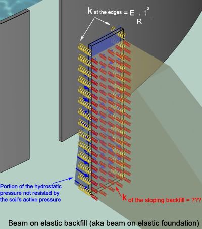
Secondly, back to the scenario where P
0 < hydrostatic pressure. Here the walls start pushing into the backfill after the at-rest pressure is fully consumed, the wall then -I think- behaves pretty much like a slab on grade. Now we have a new player: the modulus of subgrade reaction
'k' of the sloping backfill that will participate in the equilibrium of the wall subjected to the portion of hydrostatic pressure not resisted by P
0.
So, the first million dollar question is:
[COLOR=blue yellow]Does my convoluted reasoning make sense?
If so, what's the value of 'k' for the backfill ? Is it constant along the full height of the embankment?[/color]
Active Pressure
=========
Let's move on to some actual numbers from the present project:
To estimate the at-rest pressure I go back to the same Figure 24 cited above (active pressure graph):
Then, P
active = 4,048 Kg/m
2
At-rest pressure = P
0 = 1.5 x 4,048 = 6,072 Kg/m
2
To me these numbers seem unrealistically high, but again I could be wrong.
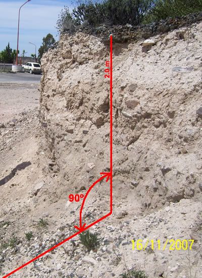
A 90º cut on the at-rest stockpiled soil that will be used for the sloping backfill suggests that active pressures, if any, can't be that big.
Even more, the soil on the picture is naturally consolidated, not mechanically compacted as is common practice with sloping backfills.
So, the second million dollar question is:
[COLOR=blue yellow]What is the "real" active pressure?
4,048 Kg/m
2 from Figure 24 ?
0 Kg/m
2 like the photo suggests ?
Or something in between ?
Is it safe to use the graphs from Figure 24, even when short cylinders represent an edge case?
[/color]
Well...this got a bit longer than I'd thought.
Anyway, I'll greatly appreciate if someone can give me an opinion on the questions set above. That would really really help me with the project.
Before I finish...
I contacted a local geotechnical specialist with 20+ years experience to provide me some guidance but he was more clueless than me on this one. At one point I sensed he was embarrassed by my questions. He said his field of expertise (translation: comfort zone) was urban construction and related stuff like SPT's, etc. Go figure.
![[sad]](/data/assets/smilies/sad.gif "[sad] [sad]")
Thanks !


![[cheers]](/data/assets/smilies/cheers.gif "[cheers] [cheers]")